Continue to Site

Welcome to EDAboard.com

Welcome to our site! EDAboard.com is an international Electronics Discussion Forum focused on EDA software, circuits, schematics, books, theory, papers, asic, pld, 8051, DSP, Network, RF, Analog Design, PCB, Service Manuals... and a whole lot more! To participate you need to register. Registration is free. Click here to register now.

Pin voltage issue

Status
Not open for further replies.

Rajinder1268

Full Member level 3
Full Member level 3
Joined
Mar 20, 2021
Messages
162
Helped
1
Reputation
2
Reaction score
4
Trophy points
18
Activity points
1,228
Hi all,
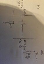
We are trying to use a FT230x CBUS3 to control the BOOT status of a STM32F215.
The boot pin of the STM32 is tied to 0V via a 10K pull down.

The internal pull up of the FT device is used to toggle the boot pin. I have attached a diagram.

We are seeing a voltage of 0.5V which does not meet the requirements for the VIH of the STM32 to register as a logic 1. It has the following criteria 1.75V<VDD<3.6V

However, when the pull down is changed to 100K we get around 2.2V.

I have measured the value of the internal pull up of the FT230 by measuring the current going into the CBUS3 pin and VCcIO is 3.3V. Which is around 66K.

This all makes sense. My question is why when the pull down is at 10K can I still enter boot mode when the voltage going into the STM32 is 0.5V? Sometimes it fails.

Thanks in advance.
 

Attachments

  • IMG_20231020_071530.jpg
    IMG_20231020_071530.jpg
    3.2 MB · Views: 119

Don't look only at DC values, consider superimposed noise. To be clearly sensed as low, input voltage must be < Vil, range between Vil and Vih is uncertain.

It may be helpful to place a small filter capacitor (e.g. 1 nF) across the input.
 

Hi,

3.2 MBytes for a couple of lines....
But no link to datasheets.

The internal pull up of the FT device is used to toggle the boot pin.
Why. Using the pullup when there is an external pull down makes no sense.
Why not properly drive the pin?

It has the following criteria 1.75V<VDD<3.6V
This is the "safe" area. This does not mean there is no grey area outside where it still detets HIGH.

why when the pull down is at 10K can I still enter boot mode when the voltage going into the STM32 is 0.5V?
I doubt this. 0.5V should be clean LOW condition.
The BOOT pin may have a special function regarding pull down and sampling timing. You need to read the datasheet.

Klaus
 

We are toggling from 0 to 1. To get into bootloader mode. However it sometimes enters this state when the Boot0 is at 0.5V. Which is confusing. With the 100K pull down it works all the time.
--- Updated ---

We have the pull down but need to toggle Boot0 to a logic 1 to get into the system memory where the bootloader resides.
 
Last edited:

Don't look only at DC values, consider superimposed noise. To be clearly sensed as low, input voltage must be < Vil, range between Vil and Vih is uncertain.

It may be helpful to place a small filter capacitor (e.g. 1 nF) across the input.
Hi,
The Boot0 is at 0V via the 10K. However, it's when try entering the Bootloader by switching it via the FTDi device. The voltage jumps to 0.5V, which is nowhere close to the ViH of the STM32, minimum is around 1.25V.
We scoped this too. But at 0.5V some units enter bootloader? I can't understand it.
 

Hi,

Instead of complaining about the obvious - the levels are not valid - why not simply "solve" the problem.
--> Just drive the FT230x correctly HIGH and LOW. And every problem is gone - no need to worry anymore.

Read it´s datasheet how to do it properly.

****
Don´t get me wrong.. What is so difficult to post a link to the datasheet?
Now I did a search, found one.
And what did I see?
1.75V<VDD<3.6V
This is not VIH, but the test condition to specify VIH. It describes the power supply.

VIH_min is specified as:
0.17VDD+0.7
Now if VDD = 3.3V, then the valid level for VIH starts at 0.17 x 3.3V + 0.7V which is 1.26V.


Pretty close at your 0.5V. Thus what you see is quite expectable.
(in green: corrected after post#7)

Klaus
 
Last edited:

Hi,

Instead of complaining about the obvious - the levels are not valid - why not simply "solve" the problem.
--> Just drive the FT230x correctly HIGH and LOW. And every problem is gone - no need to worry anymore.

Read it´s datasheet how to do it properly.

****
Don´t get me wrong.. What is so difficult to post a link to the datasheet?
Now I did a search, found one.
And what did I see?

This is not VIH, but the test condition to specify VIH. It describes the power supply.

VIH_min is specified as:

Now if VDD = 3.3V, then the valid level for VIH starts at 0.17 x 3.3V which is 0.56V.

Pretty close at your 0.5V. Thus what you see is quite expectable.

Klaus
Do you not add the 0.7V, this is what I did?
--- Updated ---

Do you not add the 0.7V, this is what I did?
Do I not need the ViH of the STM32? Not the FTDi?
--- Updated ---

Do you not add the 0.7V, this is what I did?
--- Updated ---


Do I not need the ViH of the STM32? Not the FTDi?
Ask we are putting the STM32 into Boot mode?
 

Do you not add the 0.7V, this is what I did?
My bad. You are correct. I now corrected post#6.
But "where" did you do this? In post#5 you talk about 1.25V but no information where this value comes from.

Do I not need the ViH of the STM32? Not the FTDi?
This is STM32 specification. I no where used FTDI specification.
The "i" in "ViH" means "input". Input is at the STM32 side.

Again, again, again: Drive the FTDI correctly!!!! It´s annoying that you permanently ignore the solution.
And if it does not work, tell why!

Klaus
 

My bad. You are correct. I now corrected post#6.
But "where" did you do this? In post#5 you talk about 1.25V but no information where this value comes from.


This is STM32 specification. I no where used FTDI specification.
The "i" in "ViH" means "input". Input is at the STM32 side.

Again, again, again: Drive the FTDI correctly!!!! It´s annoying that you permanently ignore the solution.
And if it does not work, tell why!

Klaus
Hi,
The design was done before I joined the company. Now they are finding issues and I am left to solve them. They don't want a PCB respin.
 

Vil= 0.43 V max Choose a lower voltage.
Hi,
The Boot0 is at 0V via the 10K. However, it's when try entering the Bootloader by switching it via the FTDi device. The voltage jumps to 0.5V, which is nowhere close to the ViH of the STM32, minimum is around 1.25V.
We scoped this too. But at 0.5V some units enter bootloader? I can't understand it.
False assumptions.

Replace 10k with <= 6k8 to get <= 0.41 for Vil = 0.43 V max = 0.1 * Vdd+0.1 V
 

i’m late to this discussion, but what i’m reading is:
1) OPs design has a 66K pullup into a 10K pull down, i.e., a voltage divider, which gives the incorrect input voltage.
2) Sometimes the input senses a high, some times not.
3) OP refuses to drive the input correctly.

Am I missing something?
 

i’m late to this discussion, but what i’m reading is:
1) OPs design has a 66K pullup into a 10K pull down, i.e., a voltage divider, which gives the incorrect input voltage.
2) Sometimes the input senses a high, some times not.
3) OP refuses to drive the input correctly.

Am I missing something?
Perhaps, unstated other requirements for the 10k resistor.

I mistook that he wanted to Vil when it is Vih, so why have a pull-down resistor at all, if the FT230X C port has 66k pullup.

Vih = 1.26 V min = 0.17 * Vdd+0.7 V If you must terminate input with a pull down resistor for some other reason, choose a value to exceed Vih with noise margin.
 

I believe it has been already explained how it's possible that you measure 0.5 V DC but the boot input is triggered though.

I understand that you are asking how to modify the circuit so that bootloader control works reliable.
I expect it's possible by increasing pull-down resistor plus connecting a parallel capacitor as noise filter.

At least when you want a "quick and dirty" solution without PCB modification.

Happy developing!
 

BOOT0 has lower thresholds than I/O ports.
Vil= 0.43 V max = 0.1 * Vdd+0.1 V
Vih = 1.26 V min = 0.17 * Vdd+0.7 V
View attachment 185622
This is where I got the 1.26V for ViH.
--- Updated ---

Perhaps, unstated other requirements for the 10k resistor.

I mistook that he wanted to Vil when it is Vih, so why have a pull-down resistor at all, if the FT230X C port has 66k pullup.

Vih = 1.26 V min = 0.17 * Vdd+0.7 V If you must terminate input with a pull down resistor for some other reason, choose a value to exceed Vih with noise margin.
The pull down is to keep the BOOT 0 pin at 0V, then switched to logic 1 via the FTDi. This has the effect of accessing the bootloader in system memory.
 

    barry

    Points: 2
    Helpful Answer Positive Rating
So what you are telling us is that the FT chip is incapable of driving more than 0.5V across a 10K resistor.

But the FT chip has a 66K pull-up, which means the MINIMUM voltage you’ll see is 0.5V. You’ll NEVER SEE LEES THAN 0.5V, if what you say is true.

MAYBE you’ve got a 66K resistor IN SERIES with the FT output, not a pull-up?
 

This is where I got the 1.26V for ViH.
--- Updated ---


The pull down is to keep the BOOT 0 pin at 0V, then switched to logic 1 via the FTDi. This has the effect of accessing the bootloader in system memory.
The simply #9 shows the correct Thresholds for 0 and 1 and so you ensure the FTDI drive current is adequate to pull up the voltage above 1.26V. With the minimum programmable drive current is +/- 2mA with Voh = 2.97 and Vdd=3.3 V , you have no problem driving 3.3k pull down up to 3V with < than 1mA

Solution : Change 10k to 3.3k unless you need to conserve power then 6.6k maximum.

* The I/O drive strength and slow slew-rate are configurable in the MTP memory.

1697847610132.png
 

The simply #9 shows the correct Thresholds for 0 and 1 and so you ensure the FTDI drive current is adequate to pull up the voltage above 1.26V. With the minimum programmable drive current is +/- 2mA with Voh = 2.97 and Vdd=3.3 V , you have no problem driving 3.3k pull down up to 3V with < than 1mA

Solution : Change 10k to 3.3k unless you need to conserve power then 6.6k maximum.

* The I/O drive strength and slow slew-rate are configurable in the MTP memory.

View attachment 185637
Why 6.6K max?The higher the pull down resistance, the lower the required current, right?
 

Status
Not open for further replies.

Part and Inventory Search

Welcome to EDABoard.com

Sponsor

Back
Top