Continue to Site

Welcome to EDAboard.com

Welcome to our site! EDAboard.com is an international Electronics Discussion Forum focused on EDA software, circuits, schematics, books, theory, papers, asic, pld, 8051, DSP, Network, RF, Analog Design, PCB, Service Manuals... and a whole lot more! To participate you need to register. Registration is free. Click here to register now.

PIC16f870 Help please

Status
Not open for further replies.

dj_holmzy

Junior Member level 2
Joined
Jun 22, 2021
Messages
21
Helped
0
Reputation
0
Reaction score
0
Trophy points
1
Visit site
Activity points
177
Hi,

I have a faulty chip that I cannot read and am trying to programme a new one for replacement. The chip is pic16f870 and it came from an amplifier. I have gone through great difficulty just to get the device to read the chip in MPLAB IDE.

I have attached the schematic of the circuit with the chip I need to programme. Any help would be greatly apprectaited as currently the amplifier does nothing as the chip is dead. Believe to be electrostatically shocked in circuit. Thank you
 

Attachments

  • S21-MI-CONTROL-CCT_.pdf
    133.5 KB · Views: 230

OK, I'm ready!

This amplifier is absolutely beautiful sounding. Very low distortion and very high output power with little to no heat when driven decently. They hold their value too.

I will now fit the new programmed chip into the board and see if I can power it externally and report back. I used this file 16F870_AVI_S21_MI.X
 

I cant as there is no space and the tracks are very fragile and already badly damaged!!

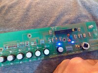
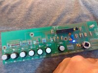
But........Its alive!!!!!! The mute LED is on and the REC LED 7 is constantly flashing!
--- Updated ---

Was the REC LED suppose to constantly blink or for 2 seconds?
 

Attachments

  • IMG_20210628_223559676.jpg
    IMG_20210628_223559676.jpg
    1.3 MB · Views: 150
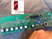
  • IMG_20210628_223600815.jpg
    IMG_20210628_223600815.jpg
    1.9 MB · Views: 149
Last edited:

OK, here is another piece of code:

Code:
Device 16F870
Xtal = 4
All_Digital = true

Reminders false
Config DEBUG_OFF, LVP_OFF, PWRTE_OFF, WDT_OFF, HS_OSC
Reminders true

Declare RC5In_Pin = PORTA.4

Input PORTA
Output PORTB
Output PORTC

Symbol IN1_LED = PORTB.0
Symbol IN2_LED = PORTB.1
Symbol IN3_LED = PORTB.2
Symbol IN4_LED = PORTB.3
Symbol IN5_LED = PORTB.4
Symbol IN6_LED = PORTB.5

Symbol REC_LED = PORTB.6
Symbol REC1_LED = PORTC.0
Symbol REC2_LED = PORTC.1
Symbol REC3_LED = PORTC.2
Symbol REC4_LED = PORTC.3
Symbol REC5_LED = PORTC.4

Symbol REC_btn = PORTA.3

Dim RC5_rcv As Word
Dim RC5_device As RC5_rcv.HighByte
Dim RC5_command As RC5_rcv.LowByte

Dim Keys As Byte
Dim Key_mask As %00000111
Dim CMask As %11100000
Dim InButtons As Byte
Dim RecButton As Bit
Dim RecStatus As Bit


' setting initial states of output pins on power up
PORTB = %00000001  ' CH1 initially selected
PORTC = 0
Clear RecStatus

' Main program loop
While 1 = 1

    GoSub CheckButtons
   
    If REC_btn = 1 And RecStatus = 0 Then
        High REC_LED
        DelayMS 50  'debouncing of REC pb
        Set RecStatus
        While REC_btn = 1
            DelayMS 10
        Wend
        GoSub CheckButtonsRec
    Else
        Low REC_LED
        DelayMS 50  'debouncing of REC pb
        Clear RecStatus
        PORTC = 0 & CMask
    End If
   
Wend
End

'****************************************************************
' * SUBs                                                        *
'****************************************************************
CheckButtons:
    InButtons = PORTA
    InButtons = ~(InButtons & Key_mask)
    Select InButtons
    Case 0
        PORTB = %00000001
       
    Case 1
      PORTB = %00000010
       
    Case 2
      PORTB = %00000100
     
    Case 3
      PORTB = %00001000
     
    Case 4
      PORTB = %00010000
     
    Case 5
      PORTB = %00100000
     
    End Select
   
'    RecButton = REC_btn
'    If RecButton = 1 Then
'        Toggle REC_LED
'    End If
   
Return

'****************************************************************
CheckButtonsRec:
    InButtons = PORTA
    InButtons = ~(InButtons & Key_mask)
    Select InButtons
    Case 0
       PORTC = %00000001 & CMask
     
    Case 1
       PORTC = %00000010 & CMask
     
    Case 2
       PORTC = %00000100 & CMask
     
    Case 3
       PORTC = %00001000 & CMask
     
    Case 4
       PORTC = %00010000 & CMask
   
    End Select
Return
and hex file in attachment.

It should also react to REC button and behave appropriately :)

Rename file to amp.hex

To be able to program your chip soldered to the PCB, you will need to solder some wires to your board and connect them to your programmer.
Needed connections are appropriately marked on board as CLK DAT MCLR and two additional for GND and VCC.
 

Attachments

  • Amp.txt
    1,000 bytes · Views: 124

I think I rather just remove the chip!

But I have no idea what to do with the file as the last one just uploaded as project and I clicked write to chip. Please can you explain what to do with the file, I'm un-soldering the chip now..
--- Updated ---

OK I renamed the file and learned how to import it but I keep getting an error:

Connecting to MPLAB PICkit 3...

Currently loaded firmware on PICkit 3
Firmware Suite Version.....01.56.09
Firmware type..............Midrange

Programmer to target power is enabled - VDD = 4.750000 volts.
Target Device ID (0xd00) is an Invalid Device ID. Please check your connections to the Target Device.

Device Erased...

Programming...

The following memory area(s) will be programmed:
program memory: start address = 0x0, end address = 0xab
configuration memory
program memory
Address: 0 Expected Value: 0 Received Value: 280a
Failed to program device
 
Last edited:

I cant as there is no space and the tracks are very fragile and already badly damaged!!

But........Its alive!!!!!! The mute LED is on and the REC LED 7 is constantly flashing!
--- Updated ---

Was the REC LED suppose to constantly blink or for 2 seconds?
Yes the test code you programmed in to PIC16F870 will flash the (record) light continuously at a rate of two flashes per seconds.
This is all this code does.

The only purpose for this code was to validate that your process for building the HEX file from XC8 C source code with the MPLABX IDE tools and programming the PIC16F870 device worked.

Now you need to update the main.c source code file in your project and build a new HEX file then reprogram your PIC16F870.

I have updated my git repository with code that implements more functionality.

You can get the updated main.c file from this link:
https://raw.githubusercontent.com/dsoze1138/16F870_AVI_S21_MI/main/16F870_AVI_S21_MI.X/main.c

There is no support for an IR remote control in this code.

What this code does:
At power on:
The (mute) light is on, all other lights are off.

Press an input select button and that input LED will light.
Press the same input select button and the (mute) light will toggle.
Press the (record) button and the (record) light above the (record) button will toggle along with the (record) light below the input select button.

This seem like a useful set of behaviors to implement.
 

What do I do with these files?

I have copied the Main.c into the same folder as 16F870_AVI_S21_MI.X and over wrote the old file. How do I build the HEX file now please?
 

What do I do with these files?

I have copied the Main.c into the same folder as 16F870_AVI_S21_MI.X and over wrote the old file. How do I build the HEX file now please?
The same way you built it the first time.

I know it's new to you but this is not like rocket science.
 

Honestly I got lost in the terminology. I copied the file Main.c across and just clicked on write to chip...

I just tried it and it exactly as you said it would behave. The real test will be tomorrow when I attach it to the amp. Needless to say I'm very excited and very thankful!!
 

After testing I can confirm the code works perfectly! Monumental achievement to be fair. Those involved know it just wouldn't have been possible without them so thank you for getting involved and sharing your wisdom. Much appreciated!
 

After testing I can confirm the code works perfectly! Monumental achievement to be fair. Those involved know it just wouldn't have been possible without them so thank you for getting involved and sharing your wisdom. Much appreciated!
I am glad you are pleased with the firmware.

(You know I only post on this forum so that you will click the "thumbs up" helped me icon on my posts) :)

If you want the IR remote control to be functional that will require you to do the hard work of describing the make and model of remote control transmitter you would like to use and which of the buttons on the remote "logically" presses which button on the amplifier. It needs to use a 36KHz IR carrier so this usually means something that uses the Philips RC5 protocol. But then most of the 38KHz Asian remote control transmitters work fairly well with the 36KHz receivers.
 
Hi,

I have a faulty chip that I cannot read and am trying to programme a new one for replacement. The chip is pic16f870 and it came from an amplifier. I have gone through great difficulty just to get the device to read the chip in MPLAB IDE.

I have attached the schematic of the circuit with the chip I need to programme. Any help would be greatly apprectaited as currently the amplifier does nothing as the chip is dead. Believe to be electrostatically shocked in circuit. Thank you
Some PIC's can be programmed to be impossible to reuse, try buying a new one off ebay, or some other dealer.
 

Some PIC's can be programmed to be impossible to reuse, try buying a new one off ebay, or some other dealer.
The original poster(OP) had a different problem. The microcontroller on his front panel had failed. Why it failed has not been mentioned.

By analyzing the schematic I created the code needed to program a new chip to make the front panel work using just the buttons. Support for the remote control is not implemented.

The OP does not have a problem programming the controller.
 
Status
Not open for further replies.

Similar threads

Part and Inventory Search

Welcome to EDABoard.com

Sponsor

Back
Top