Continue to Site

Welcome to EDAboard.com

Welcome to our site! EDAboard.com is an international Electronics Discussion Forum focused on EDA software, circuits, schematics, books, theory, papers, asic, pld, 8051, DSP, Network, RF, Analog Design, PCB, Service Manuals... and a whole lot more! To participate you need to register. Registration is free. Click here to register now.

[SOLVED] PIC Volt Meter and Battery Charging Techniques

Status
Not open for further replies.
Well ok, look if you want to learn something fresh and you have some crappy knowledge about it then you have to dump old ones and start from the beginning. If you are going to solve maths by Pakistani way, ever after 2 years you will be of nowhere. I prefer to Learn precalculus and then calculus, and study them using graphical approach and compare these phenomena with your daily life. just solving a question like a machine is no good.

back in university mt seniors made my mind that signals and systems is very difficult subject and i failed it 2 times. So it depends how you take any matter of life. Interest is the main key.

The 8051 book i recommended can be completed in 2 weeks or 1 months if u are lazy.

---------- Post added at 21:32 ---------- Previous post was at 21:29 ----------

To get more current for your supply you need external transistor with your regulator, the idea is given in Floyd's book in Regulator Chapter.
Thank you so much. i have got admission 3 days ago in COMSAT for MCS due to microcontroller but i think BCS was better any way thank you os much for ur advice. :p
Anyway is code more imporatant but ur chip work ok
i have made a numeric digital lock. i give this chip to a student of BCS final year. The code was 6 digit numeric for gate lock with keypad and the code was save in eeprom and can be changed with keypad after dialing correct code lock open for 5 sec only and code can be change by press number key within 2 sec of dialing code and need to ender new pass code twice. if u forget the code press the reset code reset button on the board after restarting the board withing 5 sec otherwise reset default canceled after 5 mins.
He like it soo much even the professors of electronics like it and test it and ask me to make it commercial but i dont know the hardware design. But later when i give the source file of its programme to that student he react as i fired at him with ak47. he said that it is like a one class child trying to write the essay on democracy so i decided to take the admission in mcs.
But question is that my PIC was working 100% correct even his teacher like it but than why he rejected it after the source file.
I think if ur code is ok and chip is working with no bug there is no problem. thats why the people did not give source code.

I have seen two PIC Programmers GENIUS G540 and BeeProg BeeProg - Universal programmer | Elnec
which one is better??
i am confused and i also orderd for a website domain .pk
a
 

OK look if you are so much interested then even BCS is not good. I studied from COMSATS Wah and i did BS(CE). Since you are interested in Hardware stuff and programming languages related to it so that would be right choice. You can change your field now or it will be late.

I like your attitude that u reacted and took admission, its a positive attitude. The reason he rejected your code is that it was not professionally written. Yes even if code is working fine there is a difference. There are certain programing style that you have to write your code so it can be easily understood by any other and it allows you keep away from normally occurring errors when you spent hours of time on programing. Secondly for example you have written a 20 line code and a professional can do it in 20 lines or less, Using of minimum variables, always keep your controller busy to get maximum efficiency. A single 8051 can control you whole house if you want to automate it. So i think using it inefficiently is its insult.

I only used G540 its been 10 months and its working quite good.
 

You mean i should take admission in BSCE not in MCS. I think they will not now allow me to chage the degree as the first class is on 5th september

---------- Post added at 19:08 ---------- Previous post was at 19:04 ----------

anyway thank you so much
I am ordering GENIUS G 540 from
**broken link removed**
 

Voltmeter made with PIC internal ADC won;t be any great. Having 10 bits resolution (besides INL, DNL, blablabla) means that with reference voltage of 4.096 volts you'll have 4mV of resolution. If you want to measure larget voltages you need to divide them.

If you want more simple design, than you can use "stiff" divider (let's say 9:1 for 40V range). In that case you would get theoretical resolution of 40 mV across whole range. If it's sufficient' then fine.

If you seek better resolution at lower voltages than you should use some dynamic voltage divider. I would consider switching between few lower resistors in a divider using some low power n-mosfet. Otherwise you can use solid state analog switch or orginary electromechanical relay to change division ratio. For sensing if the range should be chosen you need to add 5V1 zener and a resistor to prevent damage to the adc in the case of connecting like 40V when divider is set to 1:1. When your adc measures maximum value (code 0x3ff for 10 bit adc) then it means you should switch the divider to hugher division ratio. that approach makes thing a bit complicated, but gives maximum accuracy possible at any given voltage.

It is possible to use oversampling. If you assume, that the dc voltage which u are measuring contains some noise component and the LSB of an adc "flickers" with some statistic relation to the voltage between discrete levels, than you can statistically increase adc resolution. Having 10 bits of resolution with 1 LSB bit translating into 4mV, you take 2 measurements and add them together assuming that 1 LSB = 2mV. The same thing you can do to larger extent. Adding 16 values together gives you an lsb of 0.25 mV which translates into 14 bits. Of course this can't be done infinitely. You need how many effective bits of resolution you can get (just calculate as said above and compare with some very accurate measurement). I've done it on AVR and got ~12 bits of resolution.
 

Do you think you can understand master subject without doing bachelors i.e. its prerequisites?

I dont know
it is not my headache .
COMSAT give me admission so they knew better about this
The MCS classes are started on 5th of september and 3 days left in first class.
And i have no time to go to lahore for electronics parts i want to make my own parts collection
Can u believe i have only 1 PIC16F676 and a jdm programmer since the Electronics start by me
as a PIC16F819 burnt by me in the start to check the highest voltages limit
and i use it successfully for 33 sec on 12v DC just for checking maximum tolerate level as the shopkeeper said oh oh oh its very sensitive device . u need exact 5 v with this and this and bla bla bla :p
:p

---------- Post added at 20:39 ---------- Previous post was at 20:39 ----------

I can understand any thing master level or PHD level having no mathematics portion
:cool:
 

I prefer 12+12 because charging is important issue.
Alertlinks,did you ever use trickle charger kit,which have BTA16(triac),moc3021,LM324 etc for control charging.
 

Never use trickle charging, it will eat you batteries plates up, use float charging instead i.e. 13.5 -13.8V.
 
  • Like
Reactions: gugan

    gugan

    Points: 2
    Helpful Answer Positive Rating
Never use trickle charging, it will eat you batteries plates up, use float charging instead i.e. 13.5 -13.8V.
yar energy crises is another problem in pakistan
So i think floating is good but something like this as to cut the battery when battery is fully charged. may be after floating some time passed and cut
 

Never use trickle charging, it will eat you batteries plates up, use float charging instead i.e. 13.5 -13.8V.
What is float charging?In trickle charging kit(avail in local market) we can adjust charging current according to battery size.Yes at 13.5 -13.8v(adjustable with trimpot) charging current become near 200mA.In this kit TRIAC used in series of main and transformer.


I gain some information regarding trickle charger from thread listed above.
Here a member(TAHMID) describe almost trickle and float charger is same.
 

If you guys need to know way of a reliable battery charging then just ask.

Trickle charging means charging on pulse, which local ups does those its not square wave. In charge control trickle charging, duty cycle is changed to maintained current. It is a cost effective charger i.e. as it is a pulsed charger it dose not heat up that much.
Remember a company has to do marketing and they know people who are not technical will only go for low price, so they degrade the quality. They gives you warranty for 1 year or so but anything can survive in this duration.
Good chargers are really expensive and one should build one for himself.

Trickle charging and float charging is not the same at all. Suppose you have connected a comparator to your battery set at voltage reference of 15V, when your battery reaches 15V it will stop charging. battery voltage will be suddenly decreased less than 15V and then again charging starts and it keeps on happening making a square wave charging. Triac used in that charger vary current buy starting the pulse at certain degree angle.

It is said for Lead Acid batteries to charge them as quickly as possible to maintain its long life. So trickle chargers are like slow chargers.
3 types of chargers:

Slow chargers,float charger (not a trickle charger)---> very slow charging more than a day and night. No harm
Normal chargers --->charges in 8-10 hour,Should bring the voltage down to 13.5-13.8V after charging complete.
Fast chargers----> charges in 2-3 hrs.Checks are to be made at every stage.
 
Last edited:

If you guys need to know way of a reliable battery charging then just ask..

Do you have a pic micro charger or a good schematic for a 12/24V charger ?

I'm sure I remember reading some where that pulse charging was a good method and even helps recover some lost capicty. The trouble is you could to do much reading and get confused

wizpic
 
Last edited:

The is "trickle charging" kit available in market....
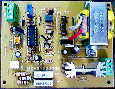
50_1314999845.jpg

Actually it is not trickle charger. It is wrongly said so. What it does is it limits the maximum current of charge. It acts like automatic dimmer. Triac is in series with transformer's primary. When current in battery lead is detected above a certain level set by pot, it dims and vice versa. It is effective in regulating the charge.
When charging current is measured of ups, a dischageed battery at 9V is charged at 30A and when it reaches 13V, it is now only 5A. So it helps protecting battery, protecting rectifier diodes and do rapid charging.
It is only a add on kit, the original battery full cut off circuit remains intact. When battery is full, charging is cut off (which is also called float charge). Battery full cut off point depends on battery type, its temperature and other factors.
In trickle charging when battery is charged at high current and reached to fully charged point instead of cutting charging instantly charging voltage is lowerd. For example if full charge is set to 14.4 volts on battery now charging voltage is set to 13.6 volts. Remember initially current is maintained and then voltage. Trickle charging is used because last 10 to 15 percent on charging can be done only thrugh this process. It is slow charging. In our situation when every 2 to 4 hours when elctricity is cut off it is useless. There is less possibility that your battey is charged through rapid charging in this time.
If you see indian ups kits this triac (better using two SCRs) phase control circuit is buit in and also controled by the micocontroller.They were using it many yeas ago. Trickle charging, you will see in switching mode chargers buit in like small chinese ups.
When battery is not in use and not properly charged, a white powder is observed on plates. It is lead sulphate.It won't let the plates to pass the current. Somtimes battery becomes useless. Pulse charging is a way to remove it by applying very high voltage pulses of very small duration for weeks. Somtimes battery is revived.
 
Last edited:

Battery plates are already very thin, and trickle charger takes away everything on it since it is burst of pulses.

I have build this charger using 8051 but on breadboard and up till now i am experimenting with it as it charges batteries well or not. Since it has been more than 8 months of charging, my battery is still healthy. I think its time to make a PCB version of it. So i will start form tomorrow and i will make a new thread and keep updating my progress.

---------- Post added at 04:16 ---------- Previous post was at 04:05 ----------

When battery is full, charging is cut off (which is also called float charge).

Cutoff is not float charging.

The proper way of battery charging is in 3 stages.

1. Constant current charge. (Helps to maintain equal voltage of every cell). Should terminate at 13.8V.
2. Constant Voltage charge. Should terminate at Ib <200 mA.
3. Standby or float charge. Can be applied to a battery for whole life. No harm.

I a mean is that a battery charging is cutoff by monitoring voltage, because in Pakistan they cut off using voltage. Only charge monitoring can tell you the charging of battery.
 

Cutoff is not float charging.
QUOTE]

From
Trickle charging - Wikipedia, the free encyclopedia


Float charger
A float charger differs from a trickle charger in having circuitry to prevent overcharging. It senses when the battery voltage is at the appropriate float level and temporarily ceases charging; it maintains the charge current at zero or a very minimal level until it senses that the battery output voltage has fallen, and then resumes charging. It is important to note that the appropriate float voltage varies significantly with the construction of the battery and the ambient temperature. With the appropriate voltage for the battery type and with proper temperature compensation, a float charger may be kept connected indefinitely without damaging the battery. With a 6-cell (nominal 12V) lead-acid battery the correct float voltage drops by about 0.15 V for a 5°C rise in ambient temperature. Not compensating for this will shorten battery life either by over- or under-charging.
Charge current at zero means cut off.


**broken link removed**

63_1315007608.gif
 
  • Like
Reactions: ggmssr

    ggmssr

    Points: 2
    Helpful Answer Positive Rating
Unfortunately Wikipedia supports my definition. Here is a useful site... batteryuniversity.com

No offense my friend. But you have to understand English meaning as well as logical meaning of it. Cut off mean to Cut as there is nothing connected to the battery, i.e. either you take off the charging terminals or switch off the power supply using some relay.

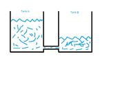
here float means equilibrium state. Consider an example of two water tanks. as in FIg.

Tank A has a higher pressure than tank B same as a changing source = tank A and the battery =tank b.

When tank B water level start increasing and tank A start decreasing. When both levels are equal, the flow of water through the pipe will be stopped. Remember the connection is still there but no flow. and when u take some water out of the tank b, flow starts again till it levels up.

In case of cutoff, introduce a valve in the pipe and as level equals i.e. no flow, close the valve. and when you take water from tank B there would be no leveling up again unless you open the valve.


The thing is we some time mix up the terminologies in our day to day life but they vary.

In case of battery changing use current monitoring and it can be accurately measure if its a constant voltage. The discharge is usually measured through battery terminal voltage level, its ok since its an easy way. But a good way to measure charge is to keep track ok discharge of current over time and subtract it through battery capacity. but this is a way too complex technique. and can be done only in a controller which support float integers.


The is "trickle charging" kit available in market....
50_1314999845.jpg

Actually it is not trickle charger. It is wrongly said so. What it does is it limits the maximum current of charge. It acts like automatic dimmer. Triac is in series with transformer's primary. When current in battery lead is detected above a certain level set by pot, it dims and vice versa. It is effective in regulating the charge.
When charging current is measured of ups, a dischageed battery at 9V is charged at 30A and when it reaches 13V, it is now only 5A. So it helps protecting battery, protecting rectifier diodes and do rapid charging.
It is only a add on kit, the original battery full cut off circuit remains intact. When battery is full, charging is cut off (which is also called float charge). Battery full cut off point depends on battery type, its temperature and other factors.
In trickle charging when battery is charged at high current and reached to fully charged point instead of cutting charging instantly charging voltage is lowerd. For example if full charge is set to 14.4 volts on battery now charging voltage is set to 13.6 volts. Remember initially current is maintained and then voltage. Trickle charging is used because last 10 to 15 percent on charging can be done only thrugh this process. It is slow charging. In our situation when every 2 to 4 hours when elctricity is cut off it is useless. There is less possibility that your battey is charged through rapid charging in this time.
If you see indian ups kits this triac (better using two SCRs) phase control circuit is buit in and also controled by the micocontroller.They were using it many yeas ago. Trickle charging, you will see in switching mode chargers buit in like small chinese ups.
When battery is not in use and not properly charged, a white powder is observed on plates. It is lead sulphate.It won't let the plates to pass the current. Somtimes battery becomes useless. Pulse charging is a way to remove it by applying very high voltage pulses of very small duration for weeks. Somtimes battery is revived.
Yes this kit.I am using it.I have a problem in adjustment.
I set volt 13.8 with trimpot(10k),and current i adjust is 10amp with blue multy turn trimpot.
When battery reaches near 13.8v,transformer produces sound like duz,duz.
Sound stop for 2 or 3 second and after that it again produces duz.
And this situation keeps on till mains failed.
What do you think from where i should search fault.
I observe pin 12 of LM324,sense battery voltage level.
 
  • Like
Reactions: gugan

    gugan

    Points: 2
    Helpful Answer Positive Rating
Status
Not open for further replies.

Similar threads

Part and Inventory Search

Welcome to EDABoard.com

Sponsor

Back
Top