Continue to Site

Welcome to EDAboard.com

Welcome to our site! EDAboard.com is an international Electronics Discussion Forum focused on EDA software, circuits, schematics, books, theory, papers, asic, pld, 8051, DSP, Network, RF, Analog Design, PCB, Service Manuals... and a whole lot more! To participate you need to register. Registration is free. Click here to register now.

PIC 18F ADC Problem (plz help)

Status
Not open for further replies.
For a stable 5 Volt supply, voltage =1023.(Full scale). Use Send_Value () to send the content of voltage variable to Hyperterminal and check what is getting printed. If it is different (it should be 1023) Check the voltage of Vref+ pin(pin 5). How the Vref+ is connected. Publish the Schematic.
 

For a stable 5 Volt supply, voltage =1023.(Full scale). Use Send_Value () to send the content of voltage variable to Hyperterminal and check what is getting printed. If it is different (it should be 1023) Check the voltage of Vref+ pin(pin 5). How the Vref+ is connected. Publish the Schematic.
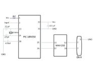
I have attached a schematic. I have not shown the schematics of MAX 232.
It doesn't show correct value for 5V input as well. The Vref is given through Vss internally as all the pins are digital except AN0, I checked the voltage in Vref (i.e pin 5) as well and its 5V. How to make it work? Please help.


Please help. I am stuck with this problem...How can I solve this problem?
 

Refresh my memory. What compiler are you using, Microchip C18 or HiTech PICC18?

Is this your last code revision?

Post #40

BigDog
 

Refresh my memory. What compiler are you using, Microchip C18 or HiTech PICC18?

Is this your last code revision?

Post #40

BigDog

I am using Microchip C18 in MPLAB IDE v8.80. Yes, the code in post 40 is my last code and schematic is in post 42 but still its not working. Please help...
 

Mr. Paritosh Giri,
I will request you once again to run the code using
void main(void)
{
ADCON0 = 0b00000001;
ADCON1 = 0;
ADCON2 = 0b10111110;
TRISA = 0b00000001;
TXSTA = 0b10100010;
RCSTA = 0b10010000;
SPBRG = 77;

while (1)
{
Delay10KTCYx(5);
ADCON0bits.GO=1;
while(ADCON0bits.GO); //dont forget the ; here
Read_ADC();
Send_Value();
Delay10KTCYx(240); //Delay 200 ms
}

}

---------- Post added at 16:06 ---------- Previous post was at 15:41 ----------

with the above main change this function also

void Read_ADC (void)
{
voltage = 0; //globally defined as unsigned long
//wait for EOC
voltage = (ADRESH << 8) | ADRESL; //combines two bytes into a long int
result = (float)(voltage * 5)/1023;
adc = result * 1000;
}
 
Last edited:

Mr. Paritosh Giri,
I will request you once again to run the code using
void main(void)
{
ADCON0 = 0b00000001;
ADCON1 = 0;
ADCON2 = 0b10111110;
TRISA = 0b00000001;
TXSTA = 0b10100010;
RCSTA = 0b10010000;
SPBRG = 77;

while (1)
{
Delay10KTCYx(5);
ADCON0bits.GO=1;
while(ADCON0bits.GO); //dont forget the ; here
Read_ADC();
Send_Value();
Delay10KTCYx(240); //Delay 200 ms
}

}

---------- Post added at 16:06 ---------- Previous post was at 15:41 ----------

with the above main change this function also

void Read_ADC (void)
{
voltage = 0; //globally defined as unsigned long
//wait for EOC
voltage = (ADRESH << 8) | ADRESL; //combines two bytes into a long int
result = (float)(voltage * 5)/1023;
adc = result * 1000;
}

I implemented your suggestion. Here's a new code:
Code:
#include <p18f4550.h>
#include <delays.h>
#include <stdlib.h>

void Read_ADC(void);
void Send_Value (void);

unsigned long adc;
unsigned float result;
unsigned long voltage;

void main(void)
{
	TRISA  = 0b00000001;
	ADCON0 = 0b00000001;	
		// A/D is ON
	ADCON1 = 0;	
		// Vref- set to Vss
		// Vref+ set to Vdd
		// AN0 is analog - others are digital
	ADCON2 = 0b10111110;
		// right justify
		// Acq time 20TAD
		// clk Fosc/64
	TXSTA = 0b10100010;
		// 8-bit
		// async
		// low speed (BRGH=0)
	RCSTA = 0b10010000;
	SPBRG = 77;
	
	while (1)
	{
		Delay10KTCYx(5);
		ADCON0bits.GO = 1;		//start converting
		while (ADCON0bits.GO);
		Read_ADC();
		Send_Value();
		Delay10KTCYx(240);		//Delay 200 ms
		Delay10KTCYx(240);		//Delay 200 ms
	}

}

void Read_ADC (void)
{
	voltage = 0;		//globally defined as unsigned long
	voltage = (ADRESH << 8) | ADRESL;		//combines two bytes into a long int
	result = (float)(voltage * 5)/1023;
	adc = result * 1000;
	//voltage = voltage * 5000;			//Vref is in milliVolts
	//voltage = voltage/1023;			//10 bit ADC
}

void Send_Value (void)
{
	char ch;
	ch = (adc/1000) % 10;		//extract thousands digit
	ch = ch + 48;			// now it is in ASCII

	while (PIR1bits.TXIF == 0);
	{
		TXREG = ch;
	}

	while (PIR1bits.TXIF == 0);
	TXREG = '.';		//We need a decimal point
	

	ch = (adc/100) % 10;		//extract hundredth digit
	ch = ch + 48;
	while (PIR1bits.TXIF == 0);
	TXREG = ch;
	

	ch = (adc/10) % 10;		//extract tenth digit
	ch = ch + 48;
	while (PIR1bits.TXIF == 0);
	TXREG = ch;


	ch = adc % 10;		
	ch = ch + 48;
	while (PIR1bits.TXIF == 0);
	TXREG = ch;

	while (PIR1bits.TXIF == 0);
	TXREG = 0x0D;

}
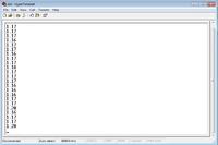
But still the result is same. Here's the attachment of output for 3.715V input. Please help me with this.


For some reason, testing the PIR1.TXIF bit makes one byte vanish. Testing the TXSTA.TRMT bit, however, works well.

I've tested once again the code on my dev board with P18F2420 @ 20MHz.
This is the working code for MikroC:
Code:
void Read_ADC(void);
void Send_Value (void);

unsigned long voltage;

void main(void)
{
  TRISA  = 0b00000001;
  ADCON0 = 0b00000001;
    // A/D is ON
  ADCON1 = 0b00001110;
    // Vref- set to Vss
    // Vref+ set to Vdd
    // AN0 is analog - others are digital
  ADCON2 = 0b10111110;
    // right justify
    // Acq time 20TAD
    // clk Fosc/64
  TXSTA = 0b10100010;
    // 8-bit
    // async
    // low speed (BRGH=0)
  RCSTA = 0b10010000;
  SPBRG = 77;

  while (1)
  {
    while (TXSTA.TRMT == 0);
    Read_ADC();
    Send_Value();
    Delay_ms(500);
  }
}

void Read_ADC (void)
{
  voltage = 0;
  ADCON0.GO = 1;
  while (ADCON0.DONE == 1);
  voltage = (ADRESH << 8) | ADRESL;
  voltage = voltage * 5000;
  voltage = voltage / 1023;
}

void Send_Value (void)
{
  char ch;
  ch = (voltage/1000) % 10;
  ch = ch + 48;

  while (TXSTA.TRMT == 0);
  TXREG = ch;
  while (TXSTA.TRMT == 0);
  TXREG = '.';

  ch = (voltage/100) % 10;
  ch = ch + 48;
  while (TXSTA.TRMT == 0);
  TXREG = ch;

  ch = (voltage/10) % 10;
  ch = ch + 48;
  while (TXSTA.TRMT == 0);
  TXREG = ch;

  ch = voltage % 10;
  ch = ch + 48;
  while (TXSTA.TRMT == 0);
  TXREG = ch;

  while (TXSTA.TRMT == 0);
  TXREG = 0x0D;
}
Only difference in the code is that I used SPBRG=207 for 20MHz Fosc.

Voltage sweep from 0V - 5V and back
adc.jpeg


I've tried to compile the code for your P18F4550 Hotfile: ADC.hex
Check the settings used if I hit it right.
settings.jpeg
 
For some reason, testing the PIR1.TXIF bit makes one byte vanish. Testing the TXSTA.TRMT bit, however, works well.

I've tested once again the code on my dev board with P18F2420 @ 20MHz.
This is the working code for MikroC:
Code:
void Read_ADC(void);
void Send_Value (void);

unsigned long voltage;

void main(void)
{
  TRISA  = 0b00000001;
  ADCON0 = 0b00000001;
    // A/D is ON
  ADCON1 = 0b00001110;
    // Vref- set to Vss
    // Vref+ set to Vdd
    // AN0 is analog - others are digital
  ADCON2 = 0b10111110;
    // right justify
    // Acq time 20TAD
    // clk Fosc/64
  TXSTA = 0b10100010;
    // 8-bit
    // async
    // low speed (BRGH=0)
  RCSTA = 0b10010000;
  SPBRG = 77;

  while (1)
  {
    while (TXSTA.TRMT == 0);
    Read_ADC();
    Send_Value();
    Delay_ms(500);
  }
}

void Read_ADC (void)
{
  voltage = 0;
  ADCON0.GO = 1;
  while (ADCON0.DONE == 1);
  voltage = (ADRESH << 8) | ADRESL;
  voltage = voltage * 5000;
  voltage = voltage / 1023;
}

void Send_Value (void)
{
  char ch;
  ch = (voltage/1000) % 10;
  ch = ch + 48;

  while (TXSTA.TRMT == 0);
  TXREG = ch;
  while (TXSTA.TRMT == 0);
  TXREG = '.';

  ch = (voltage/100) % 10;
  ch = ch + 48;
  while (TXSTA.TRMT == 0);
  TXREG = ch;

  ch = (voltage/10) % 10;
  ch = ch + 48;
  while (TXSTA.TRMT == 0);
  TXREG = ch;

  ch = voltage % 10;
  ch = ch + 48;
  while (TXSTA.TRMT == 0);
  TXREG = ch;

  while (TXSTA.TRMT == 0);
  TXREG = 0x0D;
}
Only difference in the code is that I used SPBRG=207 for 20MHz Fosc.

Voltage sweep from 0V - 5V and back
View attachment 66699


I've tried to compile the code for your P18F4550 Hotfile: ADC.hex
Check the settings used if I hit it right.
View attachment 66700

Its amazing your hex file worked like a charm for me. Its working absolutely fine now. But what was the problem in previous case? I used the same code but couldn't get it working. Can there be any problem with my compiler? I am using WinPic800 to burn the PIC and one thing I noticed was that when I loaded ur hex file, it automatically changed the setting according to the configuration but previously when I loaded my hex file, i had to make individual change to the configuration bits looking at the configuration bits from MPLAB. So was there a problem??
 

I have no idea why WinPic behaves the way you described. It should load the settings from hex file when loaded. I've never used it, sorry. I only used MPLAB for assembly years ago, and after that I switched to MikroC, mainly because I bought their dev board.

I thought your code might have some bugs, so I thought I better just send you the code that works for me so you can compare...
For example, as I remember C does not have an unsigned float (maybe microchip changed it in their implementation).

This part didn't work for me.
Code:
result = (float)(voltage * 5)/1023;
adc = result * 1000;

I don't know if it is because of the (float) modifier, or because of the unsigned float type, but I got 0.000 output with this conversion.
Anyway, it is always the best practice to multiply to the highest result, than divide. Of course, within sanity.
Here, it is the better choice since we multiply by a constant and we can anticipate the outcome.
Doing division early causes loss of precision due to round off of the result, and if you than multiply, you increase the error.

I think there was some problem with the compilation because when i loaded your hex file, the settings in WinPic changed automatically. However, i needed to manually change the setting when i loaded the hex file i created from MPLAB. I think I should switch to MikroC as well but I don't know what is required for MikroC. I don't think my current burner supports other program than WinPic. Do you think I can use MikroC with my current hardware?
 

I post no #39 I clearly indicated that
long adc;
int voltage;
float result

I never mentioned "unsigned"
 
Last edited:

Dude, did I even mentioned you?

I was referring to Paritoshgiri's code, check post #40.
Code:
unsigned long adc;
[B]unsigned float result;[/B]
unsigned int voltage;
 
Mr. bjuric,
I was telling Mr. paritosh Giri.

Thank you for your importent efforts and great solution. Thats why we all come to edaboard.
 

Mr. bjuric,
I was telling Mr. paritosh Giri.

LOL. I thought you were replying to my remark on unsigned float...

Take care. ;)
 

There is actually nothing wrong with the Microchip C18 Compiler, it has compiled the code as instructed.

There are several minor issues and one main issue with your code.

Your main issue was the following line of code:

Code:
voltage = (ADRESH << 8) | ADRESL;

The assignment statement above assumes a implicit cast conversion of a Char type to an Integer type before the final result of calculations on the Right Hand Side (RHS) of the assignment.

This implicit cast conversion is neither ANSI Standard C nor traditional C (K&R), the rule of implicit assignment type conversion or promotion, as it is sometimes referred, is as follows:

4. In an assignment statement, the final result of the calculations is converted to the type of
the variable being assigned a value. This process can result in promotion, as described in
Rule 1, or demotion, in which a value is converted to a lower ranking type.

MikroC clearly violates this rule, by the implicit type conversion of the ADRESH from type unsigned char to unsigned int before the final calculations of the RHS.

The proper way to carry out this assignment type conversion, as per ANSI Standard C rules, is as follows:

Code:
voltage = ((unsigned int)ADRESH << 8) | ADRESL;

Another option, if you do not wish to explicitly cast ADRESH from unsigned char to unsigned int, is as follows:

Code:
voltage = ADRESH;
voltage <<= 8;
voltage |= ADRESL;

In place of the statement above.

The following has been tested on a PIC18F4550 using Microchip C18 Compiler and yields the expected results:

Code:
#include <p18f4550.h>
#include <delays.h>

void Read_ADC(void);
void Send_Value (void);

unsigned int adc;
unsigned float result; 
unsigned int voltage;

void main(void)
{
	TRISA  = 0b00000001;
	ADCON0 = 0b00000001;	
		// A/D is ON
	ADCON1 = 0b00001110;	
		// Vref- set to Vss
		// Vref+ set to Vdd
		// AN0 is analog - others are digital
	ADCON2 = 0b10111111;
		// right justify
		// Acq time 20TAD
		// clk Frc
	TXSTA = 0b10100010;
		// 8-bit
		// async
		// low speed (BRGH=0)
	RCSTA = 0b10010000;
	SPBRG = 77;
	
	while (1)
	{	
		Read_ADC();
		Send_Value();
		Delay10KTCYx(240);		//Delay 200 ms
		Delay10KTCYx(240);		//Delay 200 ms
	}

}

void Read_ADC (void)
{
	voltage = 0;		//globally defined as unsigned long
    Delay10TCYx(24);       // Delay for 240TCY allow sampling cap to charge
	ADCON0bits.GO = 1;		//start converting
	while (ADCON0bits.DONE == 1);		//wait for EOC
	voltage = ((unsigned int)ADRESH << 8) | ADRESL;		//combines two bytes into a long int
	result = (float)(voltage * 5)/1023;
	adc = result * 1000;
	//voltage = voltage * 5000;			//Vref is in milliVolts
	//voltage = voltage/1023;			//10 bit ADC
}

void Send_Value (void)
{
	char ch;
	ch = (adc/1000) % 10;		//extract thousands digit
	ch = ch + 48;			// now it is in ASCII

	while (PIR1bits.TXIF == 0);
	{
		TXREG = ch;
	}

	while (PIR1bits.TXIF == 0);
	TXREG = '.';		//We need a decimal point
	

	ch = (adc/100) % 10;		//extract hundredth digit
	ch = ch + 48;
	while (PIR1bits.TXIF == 0);
	TXREG = ch;
	

	ch = (adc/10) % 10;		//extract tenth digit
	ch = ch + 48;
	while (PIR1bits.TXIF == 0);
	TXREG = ch;


	ch = adc % 10;		
	ch = ch + 48;
	while (PIR1bits.TXIF == 0);
	TXREG = ch;

	while (PIR1bits.TXIF == 0);
	TXREG = '\n';

	while (PIR1bits.TXIF == 0);
	TXREG = '\r';

	while (PIR1bits.TXIF == 0);
	
}


I should also mention the C18 Compiler comes with an extensive library of routines which could greatly simplify this task to only a few statements.

BigDog
 
Last edited:
4. In an assignment statement, is converted to the type of the variable being assigned a value. Tis process can result in promotion, as described in Rule 1, or demotion, in which a value is converted to a lower ranking type.
According to this, char (which is unsigned short) will be promoted to int.

According to MikroC reference:
short → int, long, float, or double
char → int, long, float, or double
int → long, float, or double
long → float or double


Btw, now that we are on the subject. I found that conversion on some forum because I thought it would be less confusing to the OP than the union/struct block
And now that i mentioned it, someone might find it useful.
Code:
union {
  unsigned long value;
  struct {
    unsigned short lo;
    unsigned short hi;
  };
} voltage;
.......
.......
.......
voltage.lo = ADRESL;
voltage.hi = ADRESH;
voltage.value = current.value * 5000;
voltage.value = current.value / 1023;
 

According to this, char (which is unsigned short) will be promoted to int.

According to MikroC reference:
short → int, long, float, or double
char → int, long, float, or double
int → long, float, or double
long → float or double

Such implicit cast conversions are per ANSI Standard C rules, however implicit assignment cast conversions only take place after the expression on the RHS of the assignment statement has been fully evaluated as per ANSI Standard C rules.

MikroC's evaluation of the statement in question is clearly in violation of ANSI Standard C rules.

Such nonstandard implicit cast conversions can easily become a hindrance, rather than a benefit. Not to mention the aggravation encountered when coding on an ANSI Standard C Compliant Compiler after relying on nonstandard practices of the Non-compliant MikroC compiler.

The issue encountered in the program developed in this thread is a prime example.

The C18 compiled the program as expected, the expression of the RHS was fully evaluated and THEN the result was implicitly cast by assignment from an unsigned char to a unsigned integer.

The contents of the ADRESH were shifted out of the byte and lost as was expected. Which is why the value of the variable "voltage" never exceeded "0xFF."

These are the ANSI Standard C Rules, not rules of my own creation.

While highlighting a section of the quote of the ANSI Standard C rules, I inadvertently deleted it. I've corrected the quote above and have presented it below for reference:

4. In an assignment statement, the final result of the calculations is converted to the type of
the variable being assigned a value. This process can result in promotion, as described in
Rule 1, or demotion, in which a value is converted to a lower ranking type.

By the way the quote above is not from the HiTech C Compiler Manual, but from several ANSI Standard C references, including ISO/IEC JTC1/SC22/WG14 - C: (C99) Approved standards.

BigDog
 

RHS was fully evaluated and THEN the result was implicitly cast by assignment from an unsigned char to a unsigned integer.
Never had that kind of problem so I never got into the problematics of that. Thanks for the explanation.
Btw. where the hell have you been man all this thread, you could save us all this trouble ;-)

These are the ANSI Standard C Rules, not rules of my own creation.
I never implied that.


Take care.
 

Never had that kind of problem so I never got into the problematics of that. Thanks for the explanation.
Btw. where the hell have you been man all this thread, you could save us all this trouble ;-)

Actually after reexamining the quote, I realized I had inadvertently deleted a critical phrase while attempting to highlight it in red. I have now restored the quote to its original form with the phrase intact.

If there are several people actively assisting an individual, I try not to "crowd" the thread with my input. However, if I see a possible impasse developing, like the system clock issue encountered previously in this thread, I'll jump in and lend any assistance I can.

I never implied that.

Likewise. I just want to clarify the source of the quote.

Actually, if I have the time I may rewrite the program using the libraries available in HiTech C.

BigDog
 

Status
Not open for further replies.

Similar threads

Part and Inventory Search

Welcome to EDABoard.com

Sponsor

Back
Top