Paritoshgiri
Member level 5

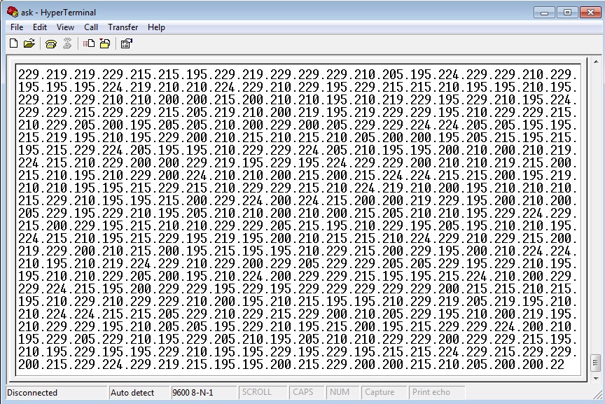
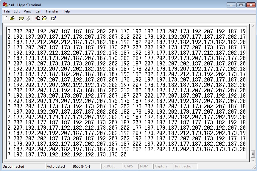
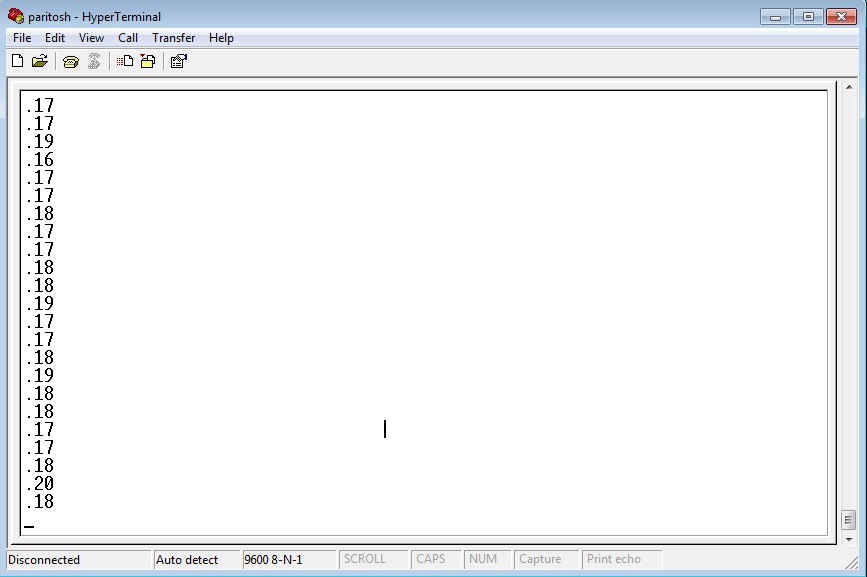
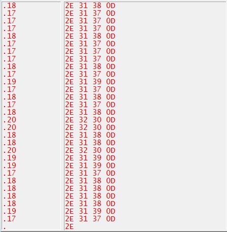
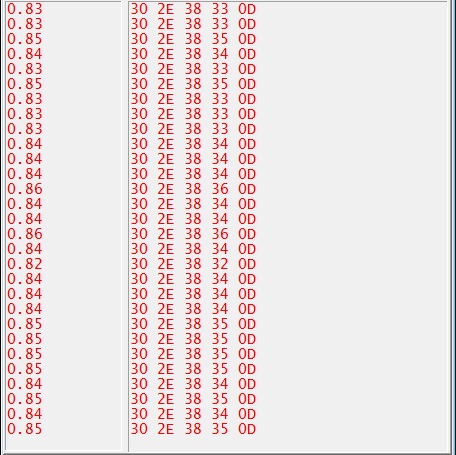
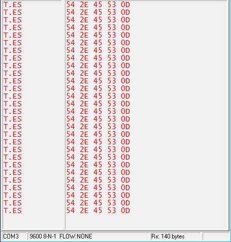
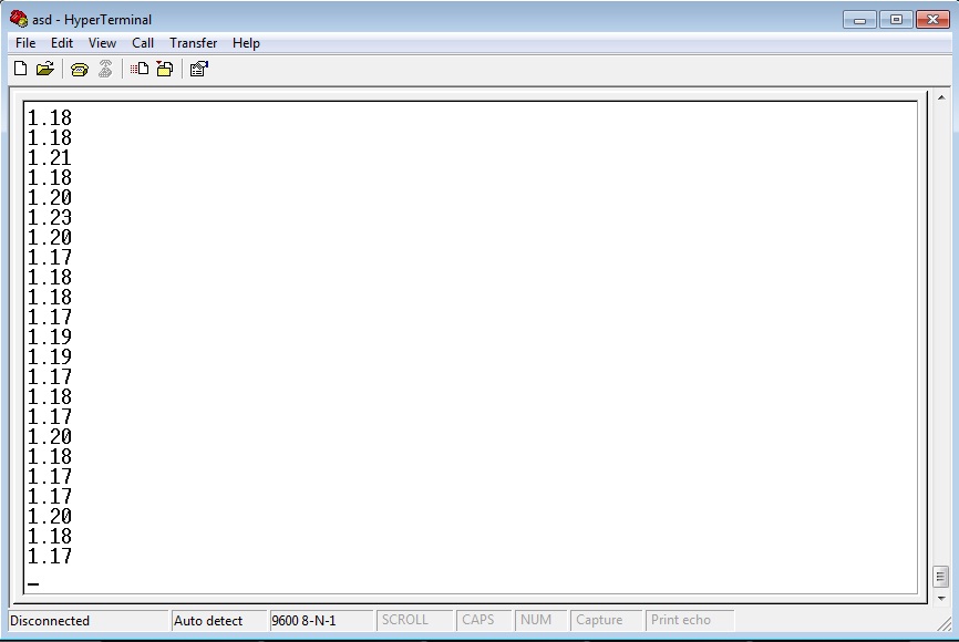
I still can't figure out the problem. When I change the input voltage, the characters in the hyperterminal changes, which means something is working. Might there be any problem with ASCII conversion? Please help....