Continue to Site

Welcome to EDAboard.com

Welcome to our site! EDAboard.com is an international Electronics Discussion Forum focused on EDA software, circuits, schematics, books, theory, papers, asic, pld, 8051, DSP, Network, RF, Analog Design, PCB, Service Manuals... and a whole lot more! To participate you need to register. Registration is free. Click here to register now.

PIC 18F ADC Problem (plz help)

Status
Not open for further replies.

Paritoshgiri

Member level 5
Member level 5
Joined
Mar 7, 2010
Messages
83
Helped
1
Reputation
2
Reaction score
0
Trophy points
1,286
Location
Kathmandu
Activity points
1,872
Hi
I am using PIC 18f4550 and I am using MPLAB IDE v8.80. I am trying to convert a sensor voltage from analog to digital. The sensor voltage range was from -10 V to + 10V, so I used MAX 232. Now after the MAX, the output is 4.416 V to 4.342 V for 0 to -10 V and 0.017 V to 0.022V for 1V to +10 V. So I input the output from MAX to AN0 and give reference 2.56 V to AN2. Here's my code:
Code:
void main(void)
{
	unsigned char L_Byte, H_Byte, bin;
	TRISD = 0;					//make port D output port
	TRISAbits.TRISA0 = 1;		//RA0 = input for analog input
	TRISAbits.TRISA2 = 1; 		//RA2 = input for Vref input
	ADCON0 = 0x81;				// Fosc/64, channel 0, A/D is ON
	ADCON1 = 0xC5;				//right justified, AN0 = analog, AN3 = Vref+
	
	while (1)
	{
		Delay10KTCYx(100);
		ADCON0bits.GO = 1;		//start converting
		while (ADCON0bits.DONE == 1);		//wait for EOC
		L_Byte = ADRESL;		//save the low byte
		H_Byte = ADRESH; 		//save the high byte
		L_Byte >>= 2;			//shift right
		L_Byte &= 0x3F;			//mask the upper 2 bits
		H_Byte <<= 6;			//shift left 6 times
		H_Byte &= 0xC0;			//mask the lower 6 bits
		bin = L_Byte | H_Byte;
		PORTD = bin;
	}
}

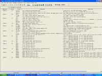
I am using 20 MHz crystal oscillator and i've also attached the configuration bits. I tried to check the outputs by putting leds in port D but in all the cases, the leds are behaving the same way. Some LEDs are blinking, some are glowing and some not glowing. What might be the main problem behind it? and how to solve it? Also, I want to view the digital signal in hyperterminal using UART. What modifications should I make for that in the code?

Please help me out. My circuit seems correct because I've successfully tested blinking leds in port B. Please Please help me with this one.
 

MAX232 is for digital communication, it won't give you any transitional values on analog change.
Any input value from -0.3V to -15V will give you +5V on output, and any value of +0.3V to +15V will output as 0V.

For your purpose you'll an differential amplifier (or instrumentation amplifier).
 

I found out that i can also use resistors to successfully covert -10 to +10 V into 0 to 5V. I am going to try that. However, what can I do to get the digital output of the PIC in hyperterminal. Can I just add the following code? How to convert this digital output into ASCII? please help me.....
Code:
TXSTA = 0x20;
	SPBRG = 20;
	TXSTAbits.TXEN = 1;
	RCSTAbits.SPEN = 1;
	while (1)
	{	
		TXREG = 'T';
		while (PIR1bits.TXIF == 0);
	}
 

To get the voltage value of ADC do this:
- use long variable
- store ADRESL to first (lower) byte and ADRESH in second byte of the variable
- multiply the variable by refference voltage*1000 (2560 for 2.56V)
- divide the variable by ADC resolution-1 (1023 for 10bit ADC)


Use modulus operator (%) to extract individual unit values. This will give you decimal value.
To convert decimal value to ASCII representation, add 48.
 

oh, just remembered...
The Vref is the maximum value you can measure with the ADC, so if you expect 0-5V, Vref should be 5V.
 

Hi;
Your approximation to change negative voltage values to positive range is wrong (you cannot use MAX232, it shifts negative and positive levels digitally, for RS232 communicaiton).
Have a check this thread;
https://www.edaboard.com/threads/233626/
https://www.edaboard.com/threads/173323/

Thank you for your help. I used 3 resistors to get the voltage swing from 0.185V to 4.717 V for -10 V to +10V. I used 3 resistors as follows:

10K from source to PIC's input
10K from PIC's input to GND
4K from PIC's input to Vcc

However, the led was not blinking correctly. Is there any problem with my coding? How can i get the digital output to hyperterminal. Please help.

---------- Post added at 08:27 ---------- Previous post was at 08:26 ----------

To get the voltage value of ADC do this:
- use long variable
- store ADRESL to first (lower) byte and ADRESH in second byte of the variable
- multiply the variable by refference voltage*1000 (2560 for 2.56V)
- divide the variable by ADC resolution-1 (1023 for 10bit ADC)


Use modulus operator (%) to extract individual unit values. This will give you decimal value.
To convert decimal value to ASCII representation, add 48.

Thank you for your reply. I think i am not getting correct digital output because leds are not blinking correctly. How can I use your suggestions in my code. Please help. I want to see the digital output in hyperterminal.
 

Here, I found something I did a while a go. I had to remove a bunch of useless stuff and rework, so it might not work 100%.
This is for MikroC, but shouldn't make much problem to understand
UART1_Write() sends character over serial
Lo() and Hi() give access to first and second byte in multi byte variables
Code:
  unsigned long voltage;     // this will hold the value (unsigned 32bit)

// reading ADC
void Read_ADC( void )
{
  ADCON0.GO = 1;                  //start ADC
  while( ADCON0.GO ){ asm nop; }  //wait for ADC to finish
  Lo(ADCvalue) = ADRESL;          // copy raw ADC values
  Hi(ADCvalue) = ADRESH;
  voltage = voltage * 3072;       // my reference was 3.072V, set this to your Vref
  voltage = voltage / 1023;       // 10bit ADC = 1024 steps (set here ADC resolution - 1)
}

void Send_Value( void )
{
  char ch;
  ch = ( voltage / 1000 ) % 10;   // extract thousand unit
  UART1_Write( 48+ch );           // convert to ASCII and send over UART
  UART1_Write( '.' );
  ch = ( voltage / 100 ) % 10;    // same principle.....
  UART1_Write( 48+ch );
  ch = ( voltage / 10 ) % 10;
  UART1_Write( 48+ch );
  ch = voltage % 10;
  UART1_Write( 48+ch );
}


// ADC initialization, check datasheet and adjust to your MCU
  ADCON0 = 0b00000001;
         //input on AN0 (RA0)
  ADCON1 = 0b00011011;
         //Vref- on VSS
         //Vref+ on AN3 (RA3)  // check datasheet and set Vref this to VCC
         //AN0:AN3 analog
  ADCON2 = 0b10111010;
         //right justified
         //20TAD
         //Fosc/64;

// UART Init, adjust for your MCU, or check if MPLAB has a function to set it for you
// in MikroC it would be just UART1_Init(); instead of all of this
  TXSTA = 0b00100110;
  RCSTA = 0b00000000;
  BAUDCON = 0b01000000;
  SPBRG = 207;            // depends on oscillator speed
  //9600bps, 8,N,1
  //BRGH = 1 (TXSTA.F2)
 

Hi Paritoshgiri;
Resistor divider network to shift negative voltages is not a good idea for your sensor output, i think. Becasue when your sensor output at a negative voltage value, then you try to source some current over your pic supply to sensor output. That is not good. Probably will cause wrong readings at your sensor output.
Instead you may be try something like this, but still there is similiar affect:?:;
MasteringElectronicsDesign.com : Design a Bipolar to Unipolar Converter to Drive an ADC
On the other hand to convert number to character issue. I assume you want to transmit any number as separate chars over the uart. ie integer number like "1012" should be transmitted as chars "1" "0" "1" "2", then you will see it on the hyperterminal screen as expected.
To achive this, there is sprintf() function in some compliers (like Hitech PicC as i know), have a search about it.
Here is a small note;
ECE101 – Basic Electrical and Computer Engineering » RS232 (or UART) Communication between your PIC and your PC
Keep in mind support of this function may depend on your compiler.
I hope this helps to you.
Good luck.
 

Here, I found something I did a while a go. I had to remove a bunch of useless stuff and rework, so it might not work 100%.
This is for MikroC, but shouldn't make much problem to understand
UART1_Write() sends character over serial
Lo() and Hi() give access to first and second byte in multi byte variables
Code:
  unsigned long voltage;     // this will hold the value (unsigned 32bit)

// reading ADC
void Read_ADC( void )
{
  ADCON0.GO = 1;                  //start ADC
  while( ADCON0.GO ){ asm nop; }  //wait for ADC to finish
  Lo(ADCvalue) = ADRESL;          // copy raw ADC values
  Hi(ADCvalue) = ADRESH;
  voltage = voltage * 3072;       // my reference was 3.072V, set this to your Vref
  voltage = voltage / 1023;       // 10bit ADC = 1024 steps (set here ADC resolution - 1)
}

void Send_Value( void )
{
  char ch;
  ch = ( voltage / 1000 ) % 10;   // extract thousand unit
  UART1_Write( 48+ch );           // convert to ASCII and send over UART
  UART1_Write( '.' );
  ch = ( voltage / 100 ) % 10;    // same principle.....
  UART1_Write( 48+ch );
  ch = ( voltage / 10 ) % 10;
  UART1_Write( 48+ch );
  ch = voltage % 10;
  UART1_Write( 48+ch );
}


// ADC initialization, check datasheet and adjust to your MCU
  ADCON0 = 0b00000001;
         //input on AN0 (RA0)
  ADCON1 = 0b00011011;
         //Vref- on VSS
         //Vref+ on AN3 (RA3)  // check datasheet and set Vref this to VCC
         //AN0:AN3 analog
  ADCON2 = 0b10111010;
         //right justified
         //20TAD
         //Fosc/64;

// UART Init, adjust for your MCU, or check if MPLAB has a function to set it for you
// in MikroC it would be just UART1_Init(); instead of all of this
  TXSTA = 0b00100110;
  RCSTA = 0b00000000;
  BAUDCON = 0b01000000;
  SPBRG = 207;            // depends on oscillator speed
  //9600bps, 8,N,1
  //BRGH = 1 (TXSTA.F2)

Thank u so much for your help. I'll try to implement this code and let you know if it works in my case. Thank you again.

---------- Post added at 16:53 ---------- Previous post was at 16:52 ----------

Hi Paritoshgiri;
Resistor divider network to shift negative voltages is not a good idea for your sensor output, i think. Becasue when your sensor output at a negative voltage value, then you try to source some current over your pic supply to sensor output. That is not good. Probably will cause wrong readings at your sensor output.
Instead you may be try something like this, but still there is similiar affect:?:;
MasteringElectronicsDesign.com : Design a Bipolar to Unipolar Converter to Drive an ADC
On the other hand to convert number to character issue. I assume you want to transmit any number as separate chars over the uart. ie integer number like "1012" should be transmitted as chars "1" "0" "1" "2", then you will see it on the hyperterminal screen as expected.
To achive this, there is sprintf() function in some compliers (like Hitech PicC as i know), have a search about it.
Here is a small note;
ECE101 – Basic Electrical and Computer Engineering » RS232 (or UART) Communication between your PIC and your PC
Keep in mind support of this function may depend on your compiler.
I hope this helps to you.
Good luck.

Thank you so much. I'll try to implement your suggestion.
 

I am still not getting the digital signal in hyper terminal. I think there's problem with serial communication because even when i tried a simple code, it didn't show anything on hyper terminal. Here's the code:

#include <p18f4550.h>
void main(void)
{
TXSTA = 0x20;
SPBRG = 20;
TXSTAbits.TXEN = 1;
RCSTAbits.SPEN = 1;
while (1)
{
TXREG = 'T';
while (PIR1bits.TXIF == 0);
}
}

The 'T' didn't appear in the hyper terminal. Is there any wrong with my configuration bits? the configuration bits are same as previous case. Please help..
 

I think your SPBRG is not right.
For 20MHz, 9600bps => SPBRG=32
and for 19200bps => SPBRG=15
 

I think your SPBRG is not right.
For 20MHz, 9600bps => SPBRG=32
and for 19200bps => SPBRG=15

Ya it is 32. But I thought I should change it into hex, so I put 20. However, I tried to put 32 as per your recommendation but still its not working. Can it be due to configuration bits problem? Please help...
 

You have PLL and PLL prescaler set. I've never used 4550, so I don't know how it all works with the MCU and USB, are they on the same frequency or not.
I didn't take the PLL into account for SPBRG earlier. Find your MCU frequency (it's not 20MHz with the PLL enabled) and use that for SPBRG calculation.

Anyhow, try disabling prescaler and PLL and see what it does. That will be 20MHz. Than when enabling PLL again, adjust the SPBRG according to new frequency.
 

The issues you are experiencing are due to the fact the PIC18F4550 is running a FOSC of 48MHz not 20MHz.

If you examine the Configuration Bit Settings in the screen shot provided you have the following settings:

FOSC => HSPLL, HS Oscillator with PLL enabled

PLLDIV => Divide by 5 with 20MHz input

CPUDIV => 1/2 (Primary Oscillator/96MHz PLL)

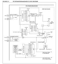
The FOSC setting utilizes HS Oscillator Input with PLL enabled. The PLLDIV of 5 is the prescaler to derive the mandatory 4MHz input to the PLL, which in turn produces a 96MHz Clock. The CPUDIV settings of 1/2 indicates if the PLL clock output is used, divide it by 2 and use the resulting clock as the system clock (FOSC).


Reference: PIC18F2455/2550/4455/4550 Datasheet, Section: 2.2.4 PLL FREQUENCY MULTIPLIER, pg 27

2.2.4 PLL FREQUENCY MULTIPLIER

PIC18F2455/2550/4255/4550 devices include a Phase
Locked Loop (PLL) circuit. This is provided specifically
for USB applications with lower speed oscillators and
can also be used as a microcontroller clock source.

The PLL is enabled in HSPLL, XTPLL, ECPLL and
ECPIO Oscillator modes. It is designed to produce a
fixed 96 MHz reference clock from a fixed 4 MHz input.
The output can then be divided and used for both the
USB and the microcontroller core clock. Because the
PLL has a fixed frequency input and output, there are
eight prescaling options to match the oscillator input
frequency to the PLL.

There is also a separate postscaler option for deriving
the microcontroller clock from the PLL. This allows the
USB peripheral and microcontroller to use the same
oscillator input and still operate at different clock
speeds. In contrast to the postscaler for XT, HS and EC
modes, the available options are 1/2, 1/3, 1/4 and 1/6
of the PLL output.

The HSPLL, ECPLL and ECPIO modes make use of
the HS mode oscillator for frequencies up to 48 MHz.
The prescaler divides the oscillator input by up to 12 to
produce the 4 MHz drive for the PLL. The XTPLL mode
can only use an input frequency of 4 MHz which drives
the PLL directly.

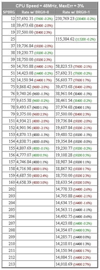
Normally the use of the TABLE 20-3: BAUD RATES FOR ASYNCHRONOUS MODES provided by the datasheet would simplify the calculation of the correct values for the desired BAUD rate, however these tables do not cover the FOSC of 48MHz.

So required calculations should be carried using the standard formulas provided for the desired BAUD rate using the now known FOSC, and double checked using one of several BAUD rate calculators available online:

PIC Microcontroller RS232 IO SPBRG Calculator


Hope the info helps in your endeavors,

BigDog
 

I am still not getting the digital signal in hyper terminal. I think there's problem with serial communication because even when i tried a simple code, it didn't show anything on hyper terminal. Here's the code:

#include <p18f4550.h>
void main(void)
{
TXSTA = 0x20;
SPBRG = 20;
TXSTAbits.TXEN = 1;
RCSTAbits.SPEN = 1;
while (1)
{
TXREG = 'T';
while (PIR1bits.TXIF == 0);
}
}

The 'T' didn't appear in the hyper terminal. Is there any wrong with my configuration bits? the configuration bits are same as previous case. Please help..


I once faced the same problem. If you are using 20MHZ crystal, then calculate value in decimal to load in SPBGR register from the given formula:-

value in decimal to load in SPBGR register =(312500/Desired Bud Rate)-1
So, for Desired Bud Rate 9600, value in decimal to load in SPBGR register =(312500/9600)-1=31.55 =32

I was successful with the same code(isnt it from Mazidi?) only after doing the following:-

Change your PCs serial poart bud rate to 9600. Device Manager-->Ports(COM & LPT)-->COM1-->Right click properties-->COM1 Port Properties(Set bits per second to 9600 and Hardware control to none). Use same setting in Hyperterminal.
 

The issues you are experiencing are due to the fact the PIC18F4550 is running a FOSC of 48MHz not 20MHz.

If you examine the Configuration Bit Settings in the screen shot provided you have the following settings:

FOSC => HSPLL, HS Oscillator with PLL enabled

PLLDIV => Divide by 5 with 20MHz input

CPUDIV => 1/2 (Primary Oscillator/96MHz PLL)

The FOSC setting utilizes HS Oscillator Input with PLL enabled. The PLLDIV of 5 is the prescaler to derive the mandatory 4MHz input to the PLL, which in turn produces a 96MHz Clock. The CPUDIV settings of 1/2 indicates if the PLL clock output is used, divide it by 2 and use the resulting clock as the system clock (FOSC).


Reference: PIC18F2455/2550/4455/4550 Datasheet, Section: 2.2.4 PLL FREQUENCY MULTIPLIER, pg 27


Normally the use of the TABLE 20-3: BAUD RATES FOR ASYNCHRONOUS MODES provided by the datasheet would simplify the calculation of the correct values for the desired BAUD rate, however these tables do not cover the FOSC of 48MHz.

So required calculations should be carried using the standard formulas provided for the desired BAUD rate using the now known FOSC, and double checked using one of several BAUD rate calculators available online:

PIC Microcontroller RS232 IO SPBRG Calculator


Hope the info helps in your endeavors,

BigDog

Thank u so much for your help. I used SPBRG = 77; and the serial communication is up and running. Thank u so much. Now how can I send the ADC output to the hyper terminal serially. I tried different ways but have not been able to achieve it yet. Please help.

---------- Post added at 13:04 ---------- Previous post was at 13:02 ----------

Here, I found something I did a while a go. I had to remove a bunch of useless stuff and rework, so it might not work 100%.
This is for MikroC, but shouldn't make much problem to understand
UART1_Write() sends character over serial
Lo() and Hi() give access to first and second byte in multi byte variables
Code:
  unsigned long voltage;     // this will hold the value (unsigned 32bit)

// reading ADC
void Read_ADC( void )
{
  ADCON0.GO = 1;                  //start ADC
  while( ADCON0.GO ){ asm nop; }  //wait for ADC to finish
  Lo(ADCvalue) = ADRESL;          // copy raw ADC values
  Hi(ADCvalue) = ADRESH;
  voltage = voltage * 3072;       // my reference was 3.072V, set this to your Vref
  voltage = voltage / 1023;       // 10bit ADC = 1024 steps (set here ADC resolution - 1)
}

void Send_Value( void )
{
  char ch;
  ch = ( voltage / 1000 ) % 10;   // extract thousand unit
  UART1_Write( 48+ch );           // convert to ASCII and send over UART
  UART1_Write( '.' );
  ch = ( voltage / 100 ) % 10;    // same principle.....
  UART1_Write( 48+ch );
  ch = ( voltage / 10 ) % 10;
  UART1_Write( 48+ch );
  ch = voltage % 10;
  UART1_Write( 48+ch );
}


// ADC initialization, check datasheet and adjust to your MCU
  ADCON0 = 0b00000001;
         //input on AN0 (RA0)
  ADCON1 = 0b00011011;
         //Vref- on VSS
         //Vref+ on AN3 (RA3)  // check datasheet and set Vref this to VCC
         //AN0:AN3 analog
  ADCON2 = 0b10111010;
         //right justified
         //20TAD
         //Fosc/64;

// UART Init, adjust for your MCU, or check if MPLAB has a function to set it for you
// in MikroC it would be just UART1_Init(); instead of all of this
  TXSTA = 0b00100110;
  RCSTA = 0b00000000;
  BAUDCON = 0b01000000;
  SPBRG = 207;            // depends on oscillator speed
  //9600bps, 8,N,1
  //BRGH = 1 (TXSTA.F2)

Thank u so much. But I tried to implement your code, but its not working. Obviously its not complete but I didn't understand how u got the voltage in the first place. I am now using a reference voltage of 5V. After getting ADRESH and ADRESL, I really don't have idea now how to send the digital output to hyperterminal. Please help.

---------- Post added at 13:06 ---------- Previous post was at 13:04 ----------

You have PLL and PLL prescaler set. I've never used 4550, so I don't know how it all works with the MCU and USB, are they on the same frequency or not.
I didn't take the PLL into account for SPBRG earlier. Find your MCU frequency (it's not 20MHz with the PLL enabled) and use that for SPBRG calculation.

Anyhow, try disabling prescaler and PLL and see what it does. That will be 20MHz. Than when enabling PLL again, adjust the SPBRG according to new frequency.

Thanks a lot. I used SPBRG = 77; for 48Mhz and serial communication is working fine. Please help me to get the digital output to the hyperterminal. Please.....
 

Thank u so much. But I tried to implement your code, but its not working. Obviously its not complete but I didn't understand how u got the voltage in the first place. I am now using a reference voltage of 5V. After getting ADRESH and ADRESL, I really don't have idea now how to send the digital output to hyperterminal. Please help.


The code is for MikroC as I said, it will not work on MPLAB, I sent it just as a reference to build from.
I also found an error in the code i sent, sorry.
Here's fixed ADC routine that might work on MPLAB.
Code:
// reading ADC
void Read_ADC( void )
{
  voltage = 0;     // globally defined as [B]unsigned long[/B]
  ADCON0.GO = 1;                  //start ADC
  while( ADCON0.GO );             //wait for ADC to finish
  voltage = (ADRESH << 8) | ADRESL;  // combines two bytes into a long int
  voltage = voltage * 5000;       // Vref is in miliVolts because we're using integers
  voltage = voltage / 1023;       // 10bit ADC
}
voltage variable is defined globally as unsigned long. It has to be long (32bit) because we're multiplying it by 5000, and it is unsigned for easier manipulation (after all there are no negative ADC values).


To send the result to hyper terminal, you need to extract separate digits using division and modulus operator and convert them to ASCII characters.
To get ASCII representation of a decimal digit simply add 48.
Code:
void Send_Value( void )
{
  char ch;

  ch = ( voltage / 1000 ) % 10; //extract thousands digit
  ch = ch + 48;                 // now it is in ASCII
  while (PIR1bits.TXIF == 0);
  TXREG = ch;

  while (PIR1bits.TXIF == 0);
  TXREG = '.';     // we need a decimal point, remember we are working in miliVolts, so the value is 1000 times higher

  ch = ( voltage / 100 ) % 10;
  ch = ch + 48;
  while (PIR1bits.TXIF == 0);
  TXREG = ch;

  ch = ( voltage / 10 ) % 10;
  ch = ch + 48;
  while (PIR1bits.TXIF == 0);
  TXREG = ch;

  ch = voltage % 10;
  ch = ch + 48;
  while (PIR1bits.TXIF == 0);
  TXREG = ch;
}

Some of this might work on MPLAB. I'm sure it needs more fixing.
Don't forget to define global variable unsigned long voltage;
 

Thank u so much for your suggestion Bjuric. I tried the following code:
Code:
#include <p18f4550.h>
#include <delays.h>

void Read_ADC(void);
void Send_Value (void);

unsigned long voltage;

void main(void)
{
	

	TRISAbits.TRISA0 = 1;		//RA0 = input for analog input
	TRISAbits.TRISA2 = 1; 		//RA2 = input for Vref input
	ADCON0 = 0x81;				// Fosc/64, channel 0, A/D is ON
	ADCON1 = 0xC5;				//right justified, AN0 = analog, AN3 = Vref+
	Read_ADC();

	TXSTA = 0x20;
	SPBRG = 77;
	TXSTAbits.TXEN = 1;
	RCSTAbits.SPEN = 1;
	Send_Value();
	

}

void Read_ADC (void)
{
	voltage = 0;		//globally defined as unsigned long
	ADCON0bits.GO = 1;		//start converting
	while (ADCON0bits.DONE == 1);		//wait for EOC
	voltage = (ADRESH << 8) | ADRESL;		//combines two bytes into a long int
	voltage = voltage * 5000;			//Vref is in milliVolts
	voltage = voltage/1023;			//10 bit ADC
}

void Send_Value (void)
{
	char ch;
	ch = (voltage/1000) % 10;		//extract thousands digit
	ch = ch + 48;			// now it is in ASCII

	while (PIR1bits.TXIF == 0);
	TXREG = ch;
	
	while (PIR1bits.TXIF == 0);
	TXREG = '.';		//We need a decimal point

	ch = (voltage/100) % 10;		//extract hundredth digit
	ch = ch + 48;
	while (PIR1bits.TXIF == 0);
	TXREG = ch;

	ch = (voltage/10) % 10;		//extract tenth digit
	ch = ch + 48;
	while (PIR1bits.TXIF == 0);
	TXREG = ch;

	ch = voltage % 10;		
	ch = ch + 48;
	while (PIR1bits.TXIF == 0);
	TXREG = ch;
}

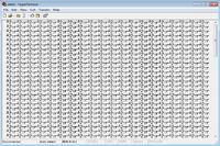
But there's still some error. I've attached what I received on hyperterminal. Where might be the problem? Is there any problem with ADCON registers? Please help me. I check the input voltage as well as reference voltage as well. They are all fine.


Status
Not open for further replies.

Similar threads

Part and Inventory Search

Welcome to EDABoard.com

Sponsor

Back
Top