Continue to Site

Welcome to EDAboard.com

Welcome to our site! EDAboard.com is an international Electronics Discussion Forum focused on EDA software, circuits, schematics, books, theory, papers, asic, pld, 8051, DSP, Network, RF, Analog Design, PCB, Service Manuals... and a whole lot more! To participate you need to register. Registration is free. Click here to register now.

Need advice for my toroidal core dimensions

treemon

Member level 3
Member level 3
Joined
Nov 2, 2022
Messages
60
Helped
0
Reputation
0
Reaction score
4
Trophy points
8
Activity points
402
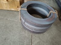
I am in need to build a 5kw inverter based on EGS002, for which I am first building a toroidal transformer, I got the toroidal core manufactured & delivered from a vendor.

Having no prior experience in doing this, I just used an android app called TransCalc to calculate core dimensions (and winding data), now I feel like core is bit awkward shape more like a ring.

My core dimensions are (mm)
OD=220
ID=150
Height=100

Weight 16kg
Material CRGO

I feel I had given too big ID, but I had to do because app told me to do so, large ID so large window area, which made core to transformer more power. According to calculation this can transfer almost 5kw..

Now I am little in dilemma whether to go ahead with this core, further put effort and also money on copper wires, already plenty of money is spent on core.

My main concern is, this look somewhat different from cores that companies are using in their inverter, should the core have a particular "form" for better efficiency, I mean the ratio of ID/OD/H must stick to some guideline?

I need suggestion from eda members, guide me whether if this core design is horribly wrong in that case I will not go ahead with this core, or if the core sizing s fine...please tell me.
 

Attachments

  • IMG-20230313-WA0002.jpg
    IMG-20230313-WA0002.jpg
    131 KB · Views: 276
There are people on that other Forum that have designed and wound a great many of these large toroidal transformers and all by hand.
Your very first effort will not look as neat as theirs ! But it will definitely work just as well, and that is what matters
One thing came up is, hoop can have 2 (or more) grooves for wire loading, this will allow multiple strand in single round.

But if any one of strand is slacking or getting shorter than other then it may become annoying, although here we release wire of sufficient length but still when you are doing 100m wire it can add up

Next thing is hoop material should be non metallic like plastic, else it can damage coating on wire

I am thinking possibility of 3 strand for secondary, as you mentioned there will noticeable heating
 
Last edited:
Three strands laid together side by side in four full layers should be possible.

First layer about 80 turns of three parallel wires should fit easily onto the core (86 turns theoretically possible).
Each successive layer will have slightly less available circumference. Four layers should do it.
The tape insulation between layers will use up a lot more space than you might be expecting.
Just put on four full layers, the exact number of turns you finally end up with is not all that critical.

That will potentially be a 30 amp winding and 7Kw.

An alternative way to do this might be to try and find three plastic spools that are no more than 100mm in outside diameter. The hole in your toroid is unusually large, and as you will be fighting with three separate wires, that might eventually prove to be less trouble than the hoop method.

The hoop works best with a single wire, where the hole in the toroid is too small to do it any other way.
Yes, I will look for right sized spool, and start winding...
 
maxresdefault.jpg

EGS002 design does not show the obvious thermal failure or dead-time shootthru or deadtime clamp diodes for a sine inverter which is necessary for a linear push-pull. It has no current sensing on the full bridge and will fail under certain conditions but work ok in demo with no load.

I suggest you find a design that specifies heat rise and deadtime under load with a true sine inverter. It must have current feedback to be reliable because the FET Vgs tolerance for linear conductance spans a 2: 1 range unlike BJT's where drive voltage might be +/-10% about mid range.
--- Updated ---

When using the sine inverter test on a 150 W lamp, which has relatively low reactance, you are not stress testing for shoot-thru failures..
 
Last edited:
maxresdefault.jpg

EGS002 design does not show the obvious thermal failure or dead-time shootthru or deadtime clamp diodes for a sine inverter which is necessary for a linear push-pull. It has no current sensing on the full bridge and will fail under certain conditions but work ok in demo with no load.

I suggest you find a design that specifies heat rise and deadtime under load with a true sine inverter. It must have current feedback to be reliable because the FET Vgs tolerance for linear conductance spans a 2: 1 range unlike BJT's where drive voltage might be +/-10% about mid range.
--- Updated ---

When using the sine inverter test on a 150 W lamp, which has relatively low reactance, you are not stress testing for shoot-thru failures..
I didnt understand many terms here, my egs002 module has temperature sensor, a current sensor, and a fixed deadtime control mechanism...

Its true that I did basic demo using egs002 module on a 250w transformer, that time i didnt had good confidence on output it produced, I thought replacing transformer to a real big kw type will do the job.

Is there any alternative to egs002 in your mind?

Also what is your take on square wave inverters, they have a bad reputation, but can they be viable option?
 
Motors have a wide dynamic impedance range of about 100:1 and eddy current losses are minimized using Sine drive such as in VFD where AC motors accelerate with fix V/f to limit peak current. The choice of transformer greatly depends on the method on the limited bandwidth of all power transformers generally to < 2 decades. So CRGOS is not well suited for low loss at 50 kHz but very effective at 50 Hz. So Ferrite is preferred for SMPS which have much lower hysteresis, but unfortunately, also much lower mu and CM filters are necessary with DM filters to reduce harmful noise.

For example my square wave car inverter causes squealing noise with a laptop charger , which does not bother me when loaded but louder when not charging, but if I use the laptop for audio output to a power amp, it will pick up EMI and cross over to the audio. ( But this is old school, now my car has BT and USB drive input, so I can program my own music. with 64 GB+ stick.
 
Last edited:
Treemon,
The original purpose of this thread was to wind a suitable toroidal inverter transformer.
Get that out of the way first, it will be required anyway whatever electronics you finally decide upon to drive it.

I honestly think think step two might be for you to move over to The Back Shed Forum. You will find that its a far more helpful and friendly Forum than here.
You will get genuine help over there, not just snarky unhelpful criticism.

The guys over there are experts at this, they have been home building transformer inverters for several decades.
There is a long rich history of continuous inverter development over there, which is still ongoing.

Its true though that the EGS002 has is problems, and is now becoming harder to find. The guys over at the Back Shed have solved all of those kinds of issues, and there are low cost alternatives that have proven reliable.

I have had just about enough of the giant egos here on EGA, people trying to demonstrate how smart they are without trying to be genuinely helpful to the less experienced.
I will see this thread through to the end.
Then no more after that here for me.
 
Motors have a wide dynamic impedance range of about 100:1 and eddy current losses are minimized using Sine drive such as in VFD where AC motors accelerate with fix V/f to limit peak current. The choice of transformer greatly depends on the method on the limited bandwidth of all power transformers generally to < 2 decades. So CRGOS is not well suited for low loss at 50 kHz but very effective at 50 Hz. So Ferrite is preferred for SMPS which have much lower hysteresis, but unfortunately, also much lower mu and CM filters are necessary with DM filters to reduce harmful noise.

For example my square wave car inverter causes squealing noise with a laptop charger , which does not bother me when loaded but louder when not charging, but if I use the laptop for audio output to a power amp, it will pick up EMI and cross over to the audio. ( But this is old school, now my car has BT and USB drive input, so I can program my own music. with 64 GB+ stick.
Some points noted.

But my transformer will be used at 50hz, mosfet output will be filtered before they go in primary.

And it seems efficiency of my transformer, will be impacted if I go with square wave, this is not desirable.
--- Updated ---

Motors have a wide dynamic impedance range of about 100:1 and eddy current losses are minimized using Sine drive such as in VFD where AC motors accelerate with fix V/f to limit peak current. The choice of transformer greatly depends on the method on the limited bandwidth of all power transformers generally to < 2 decades. So CRGOS is not well suited for low loss at 50 kHz but very effective at 50 Hz. So Ferrite is preferred for SMPS which have much lower hysteresis, but unfortunately, also much lower mu and CM filters are necessary with DM filters to reduce harmful noise.

For example my square wave car inverter causes squealing noise with a laptop charger , which does not bother me when loaded but louder when not charging, but if I use the laptop for audio output to a power amp, it will pick up EMI and cross over to the audio. ( But this is old school, now my car has BT and USB drive input, so I can program my own music. with 64 GB+ stick.
Some points noted.

But my transformer will be used at 50hz, mosfet output will be filtered before they go in primary.

And it seems efficiency of my transformer, will be impacted if I go with square wave, this is not desi
Treemon,
The original purpose of this thread was to wind a suitable toroidal inverter transformer.
Get that out of the way first, it will be required anyway whatever electronics you finally decide upon to drive it.

I honestly think think step two might be for you to move over to The Back Shed Forum. You will find that its a far more helpful and friendly Forum than here.
You will get genuine help over there, not just snarky unhelpful criticism.

The guys over there are experts at this, they have been home building transformer inverters for several decades.
There is a long rich history of continuous inverter development over there, which is still ongoing.

Its true though that the EGS002 has is problems, and is now becoming harder to find. The guys over at the Back Shed have solved all of those kinds of issues, and there are low cost alternatives that have proven reliable.

I have had just about enough of the giant egos here on EGA, people trying to demonstrate how smart they are without trying to be genuinely helpful to the less experienced.
I will see this thread through to the end.
Then no more after that here for me.
Hi warpspeed,

I was just asking him..., actually I already had plan in mind to take out additional tapping point for square wave type.. Mainly because I was not highly confident on egs002 from the beginning.

But sinewave is my preferred choice in all cases...

Earlier I couldnt open backshed forum link, I think IP is banned by ISPs here, but I will find a way to fix it.
 
Last edited:
Sine wave inverter is going to be vastly better for you in all respects.
You might be able to get a VPN to bypass some of the internet issues.
There must be some way around the problem, The Back Shed is a very benign and friendly Forum absolutely no reason to block it.

Quite right, the transformer only sees a 50Hz sine wave, so strip wound steel core will be fine.
The series choke requires some thought, but we can look at that in some depth as a separate exercise later.

First the secondary, then the primary, then the series choke
 
The Back Shed is a very benign and friendly Forum absolutely no reason to block it
What might have happened is, sometime forum had moved to a new web hosting provider which assigned them an IP that was in ban list in some countries.

Or it is possible that forum is on a shared IP

Ideally ISPs should periodically refresh ban list, but sometimes they forget.

Due to immense pressure from my other tasks as my primary field of work is coding, I will get time to wind at some later date.

Last year I started learning electronics bit by bit, because tough times are ahead, and such skill would be life saving.
 
You obviously know a lot more about the IT side of things than I do.
No hurry on the transformer, its a MAJOR project in itself.
Yes, I realize it, that is why I am doing it step by step, big uncertainty were on core & copper procurement sides.

If some difficulty is faced using egs002 then I should be able to use in a square wave mode, thats why its needed.

I left IT field long time ago, I do programming to solve my own needs, still some are in urgent state and pending from a long time.

Most people here do not realize that time for IT industry is up... :) entire field was a money laudering hack, a means to park money by ultra rich... It is also a dollar distribution network for USA.

Because to maintain dollar reserve status they also needed to ensure other countries have dollar in their account, that is why this IT stuff is there, to receive free dollar.

With the end of dollar being reserve currency, IT industry will reach its demise.
 
Tough financial times ahead for many of us in the West when (not if) the US petrodollar dies.

But also new opportunities should open up for some.
I see the future as being able to improvise, and repair/modify/recycle older equipment to keep it running, rather than writing code.
India already has a demonstrated ability to be able to do that more efficiently than just about anywhere else.
 
Tough financial times ahead for many of us in the West when (not if) the US petrodollar dies.
It will happen for sure, becuase a "reserve currency" is not something the world really needs to operate, but global trading would be severely impacted... Cuz now you have lot less money.

repair/modify/recycle
Yes

India already has a demonstrated ability to be able to do that more efficiently than just about anywhere else.
Indian IT industry is not what most people believe, work happens there correlates with maybe less than 10% of their economic activities.

Globally rich people, took no time to figure out "software" can be best tool to evade taxes, and route money... because being a non-tangible asset software can be priced anything.

A 500$ worth software most of which non-intuitive by indian IT space are invoiced for million dollar. As we see, this industry served vested interest of many groups..including US govt.
 
Agree, much of IT is a scam, but not all of it.
Typically, senior management says, our product has a bug in it, how much is it going to cost us to fix it ?

Head software guy. "I will need to employ twelve more people for six months and contract two highly priced consultants for three months"
What he knows privately, that subroutine with the bug can very likely be fixed by one guy in one afternoon.
But he wants a bigger budget to build his empire with, so he gets his money.

Pretty cynical stuff, but I have seen a lot of that both in Government and private industry.
 
Last edited:
Agree, much of IT is a scam, but not all of it.
Typically, senior management says, our product has a bug in it, how much is it going to cost us to fix it ?

Head software guy. "I will need to employ twelve more people for six months and contract two highly priced consultants for three months".
What he knows privately, that subroutine with the bug can very likely be fixed by one guy in one afternoon.
But he whats a bigger budget to build his empire with, so he gets his money.

Pretty cynical stuff, but I have seen a lot of that.
Actually he knows that 10 workers budget will be happily alloted, if he ask more it will be granted.

So he is not really cheating them, scam part starts somewhere in upstream, something very dark about these IT business, when all other industry try to be efficient, manage their cost... IT doesnt follow that... Foul smell is lot of these IT shops are run by non techie types

For india whole economy is indirectly depend on IT, including realestate, automobile and finance

if this goes, ship will sink ... In current geopolitics I am sure one event is lined up for US to ban software outsourcing.
 
TL;DR all comments
You need an LCR meter to test what you have with N^2 minimal turns for L and C from inner to outer insulated laminations. Use wire gauge you intend to use or bigger for low DCR for these tests.

Learn about hysteresis and eddy current losses and borrow a scope then learn how to test BH curve.
CRGOS are rated in losses W/kg generally less with thinner.
Then report results
Also a larger ID increases L and leaves room for windings.

It is important to measure what you have before spending a lot more and you need measurement equipment to do this right. Check the used market on Banggood.

FWIW: https://www.iqsdirectory.com/articles/electric-transformer/toroidal-transformer.html
 
Last edited:

LaTeX Commands Quick-Menu:

Similar threads

Part and Inventory Search

Welcome to EDABoard.com

Sponsor

Back
Top