Continue to Site

Welcome to EDAboard.com

Welcome to our site! EDAboard.com is an international Electronics Discussion Forum focused on EDA software, circuits, schematics, books, theory, papers, asic, pld, 8051, DSP, Network, RF, Analog Design, PCB, Service Manuals... and a whole lot more! To participate you need to register. Registration is free. Click here to register now.

Need advice for my toroidal core dimensions

treemon

Member level 3
Member level 3
Joined
Nov 2, 2022
Messages
60
Helped
0
Reputation
0
Reaction score
4
Trophy points
8
Activity points
402
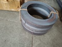
I am in need to build a 5kw inverter based on EGS002, for which I am first building a toroidal transformer, I got the toroidal core manufactured & delivered from a vendor.

Having no prior experience in doing this, I just used an android app called TransCalc to calculate core dimensions (and winding data), now I feel like core is bit awkward shape more like a ring.

My core dimensions are (mm)
OD=220
ID=150
Height=100

Weight 16kg
Material CRGO

I feel I had given too big ID, but I had to do because app told me to do so, large ID so large window area, which made core to transformer more power. According to calculation this can transfer almost 5kw..

Now I am little in dilemma whether to go ahead with this core, further put effort and also money on copper wires, already plenty of money is spent on core.

My main concern is, this look somewhat different from cores that companies are using in their inverter, should the core have a particular "form" for better efficiency, I mean the ratio of ID/OD/H must stick to some guideline?

I need suggestion from eda members, guide me whether if this core design is horribly wrong in that case I will not go ahead with this core, or if the core sizing s fine...please tell me.
 

Attachments

  • IMG-20230313-WA0002.jpg
    IMG-20230313-WA0002.jpg
    131 KB · Views: 276
O/k, there is another less convenient way to go about all this.

Start by winding a test coil on your toroid of about 1.3 turns per volt.
If your transformer is 50 volts, try perhaps 65 turns to begin with.
That should produce close to 1 Tesla at 50 Hz.
Measure the applied voltage (50v) and the current in the test winding.
A rough as guts wild guess might be in the region of 500mA to 1 amp. (25 VA to 50 VA measured)

Try more measurements using a very slightly different turns count.
The voltage probably will not change very much, but the measured current certainly will.
Ok, I done first testing (picture attached)

I did exactly 65 turns, as TransCalc app also tells same for 50vac input, I measured 0.15A idle current and voltage remains near ~50, this feels like flux density of core maybe higher than we expected.
 

Attachments

  • IMG_20230330_122157_724.jpg
    IMG_20230330_122157_724.jpg
    1.8 MB · Views: 150
at 230Vac the current ( true rms ) will be more than 5 x 0.15, but still acceptable, as a fair bit of this is inductive

and some is resistive, running the core at 230V with 325 T over several hours will cause the core temp to rise and you can see for yourself if the temp rise is acceptable ....
 
There are a few interesting unknowns which this test reveals.

The permeability of the core material determines the inductance, and the inductive reactance, which is one aspect of the measured current. Quality of the steel in the core, its alloy, and subsequent heat treatment.
Also, eddy current loss and hysteresis loss can only be measured by an actual test.
Is it premium material, or third world junk ?

Anyhow, all things considered, 150 mA falls well within the expected range of 100mA to 1 Amp (spectacularly good to not so good) at about one Tesla level of excitation at 50Hz.

So with a magnetizing power at one Tesla is about 50v x 150mA or 7.5 watts core loss, which is excellent for a multi kilowatt capable core.
You have scored yourself some very nice steel toroids there !
A wonderful start.

Bearing in mind that 1 Tesla is going to work very well as a design flux density, we now can plan some windings, if we assume that 1.3 turns per volt will produce a very satisfactory core loss and final inverter idling power figure.

The suggested current density in the wire might be 4 amps per square mm, which has proven to be a good figure for a home built inverter. Once again that is fairly conservative compared to commercial transformers, but we are not trying to build something cheap to sell as a profit making enterprise, but something really superior and efficient that we can be truly proud of.

More on the windings later.
 
Last edited:
50V x 0.15A is not 7.5 watts, it is 7.5VA - it is hard to tell the hysteresis losses unless you can see the shape of the current ( peaky at the zero crossings ) the core losses could be anywhere in the range 3 - 5 watts.

In any event the peak B = Erms / ( 4.44 F N Ae ) = 1T

Given the losses are <7.5 watts for the entire core(s), it appears you could easily go to 1.25 T
 
All you say is true. The resistive core loss is going to be less than 7.5 watts.

It would certainly be possible to increase the flux density and also the idling power losses, but why do that ?

As we will see, this core is still capable of well over 10Kw at this low flux density.
 
at 230Vac the current ( true rms ) will be more than 5 x 0.15, but still acceptable, as a fair bit of this is inductive

and some is resistive, running the core at 230V with 325 T over several hours will cause the core temp to rise and you can see for yourself if the temp rise is acceptable ....
For 230 vac I will have to add more turns which will increase overall impedance, thus keeping current about the same... Is this assumption correct or not?

I will worry, if idling power (core losses) are hitting 20watt or above, I need it to well below commercial inverters because I am using toroidal core, and not compromising on winding materials.

--- Updated ---

There are a few interesting unknowns which this test reveals.

The permeability of the core material determines the inductance, and the inductive reactance, which is one aspect of the measured current. Quality of the steel in the core, its alloy, and subsequent heat treatment.
Also, eddy current loss and hysteresis loss can only be measured by an actual test.
Is it premium material, or third world junk ?

Anyhow, all things considered, 150 mA falls well within the expected range of 100mA to 1 Amp (spectacularly good to not so good) at about one Tesla level of excitation at 50Hz.

So with a magnetizing power at one Tesla is about 50v x 150mA or 7.5 watts core loss, which is excellent for a multi kilowatt capable core.
You have scored yourself some very nice steel toroids there !
A wonderful start.

Bearing in mind that 1 Tesla is going to work very well as a design flux density, we now can plan some windings, if we assume that 1.3 turns per volt will produce a very satisfactory core loss and final inverter idling power figure.

The suggested current density in the wire might be 4 amps per square mm, which has proven to be a good figure for a home built inverter. Once again that is fairly conservative compared to commercial transformers, but we are not trying to build something cheap to sell as a profit making enterprise, but something really superior and efficient that we can be truly proud of.

More on the windings later.
Core was sourced from a Mumbai based manufacturing company, he said M4 grade CRGO steel, he also did heat treatment for 24 hours, cost of core was about 70 USD (tax included), plus transport charges.

So far I assumed flux density is some constant that depend on material, now going through your posts again, I am understanding, we can tweak it, and voltage per turn will change.

BTW test we just did, does it yield any deterministic upper limit of flux density(T)...

Naturally I wish to keep the primary turns small, but not at the cost of heating, idle consumption or any or other side effects.

Another pressing issue is, I may have to use aluminium wire, because the copper sellers are trying to rob me, I will just need a 25% thicker wire... I found some listing on anodized aluminium wire, can I use them, or enameled type is necessary?
 
Last edited:
For 230 vac I will have to add more turns which will increase overall impedance, thus keeping current about the same... Is this assumption correct or not?
--- Updated ---


Core was sourced from a Mumbai based manufacturing company, he said M4 grade CRGO steel, he also did heat treatment for 24 hours, cost of core was about 70 USD + 18% taxes, plus transport charges.

So far I assumed flux density is some constant that depend on material, now going through your posts again, I am understanding, we can tweak it, and voltage per turn will change.

BTW test we just did, does it yield any deterministic upper limit of flux density(T)...

Naturally I wish to keep the primary turns small, but not at the cost of heating, idle consumption or any or other side effects.

Another pressing issue is, I may have to use aluminium wire, because the copper sellers are trying to rob me, I will just need a 25% thicker wire... I found some listing on anodized aluminium wire, can I use them, or enameled type is necessary?
Those are good cores, you bought very well.

When you increase the turns for 230v (230v x 1.3v/turn = 299 turns) the core loss stays the same as at 50 volts and 65 turns. The current will decrease as the 7.5 VA stays the same also. That is why the testing voltage does not matter, its the volts per turn, and flux swing that matters.

Flux swing can be anything from zero up to the onset of saturation. However core losses and magnetizing current rise in an ever steepening curve. Try reducing the turns on your 65 turn test coil in steps, and measure the resulting current. Fifty two turns should produce somewhere around 1.25 Teslas. Try that and see.

The figure of one Tesla is a good starting point where the core material is of an unknown quality. I agree it's a bit low for really good material, but many secondhand toroids originate from trashed Chinese inverters, and the steel can vary a lot in quality. These Chinese cores are still popular because often they can be had free from a rubbish tip. So designing for one Tesla is a reasonable stab in the dark with a core of unknown provenance.

In that case, one Tesla should still give reasonably good results with poor core material, but pushing the flux density much higher can result in disappointingly high inverter no load idling current with inferior core material.

As it turns out, your cores are much larger than really required for 5Kw, which opens up quite a few options.
You can keep the flux density very low and take advantage of the absolutely minimal idling power.
That requires more turns, but there is plenty of room on those cores to do that.
All the extra space would also allow for aluminium wire, if 5Kw is still your goal.

5Kw should still be possible with only a single core, but that would require doubling the number of turns.
Later when you get into planning how the actual windings will fit into the available space, it can become more challenging where the core is marginal in size. Sometimes you need to push the flux density higher to reduce turns to get it to fit the core. Its all a series of tradeoffs.

I will be interested in what Easy Peasy comes up with. He is great at criticizing, but he has not really offered anything helpful or constructive to this project so far.
Superb..!!

You have answered all my doubts, I feel much relaxed..

As this is a step up transformer, and I plan to work it on 48v batteries, we have kind of already tested idling current, no need to find @ 230vac

I ended up having extra large core because of that TransCalc app, it was fixing some upper limit of power that transformer can handle, and there it depends on core cross section + ID.

So If I tried to increase power by adding more turns then that upper limit was triggered... I am not sure if app mislead me.

Certainly I will go with absolute minimum idling power... as you recommended. One more thing remained - is it possible to use anodized aluminium wire for winding?
 
Last edited:
You are quite right, in the end power is roughly proportional to cross section + ID.

What does change though are the proportions of steel and copper to do the job.
A skinny core with a big hole requires more turns, and hence more wire.
A fatter core with a smaller hole, a lot more steel, but fewer turns and less copper.

Its been quite a few years since I looked at all of that (I am now well into retirement). Several years ago both steel and copper both cost about $18 Australian dollars per kilogram to buy brand new. Lerge transformers weighing several tens of kilograms become very expensive, just for the materials.

I also know that the supply situation in India is vastly different to here in Australia.
Here we can source scrapped Chinese inverters very readily for virtually nothing, and get both the wire and the core at almost no cost at all.
Its then just a great deal of very physical work to rewind it all into something much more useful.

I am told that in India NOTHING is just thrown away into land fill as it is over here. Everything is salvaged, stripped, and the parts all sold off in the markets by some very sharp traders. A totally different situation.

I have no personal experience using aluminium wire, so cannot really comment on the reliability or usefulness of recovered aluminium wire.

I think you need to look at the cores you have, the available space, what minimum gauge wire is needed to carry the current, number of turns, and then try to source something that is going to work. Many different possibilities, there is not just one single correct answer.
--- Updated ---

O/k I am leaving myself open to another attack by Easy Peasy here, but the next consideration is the available winding area. A simple approach is to allot half the area of the hole for the primary, and half for the secondary.
That is not strictly correct, as the primary is wound over the secondary and will have a longer mean length of turn.

But anyway, if your bare hole starts off as 150mm diameter, half that area (for the primary) will be root two or 0.7071 times that diameter. So after you have wound on the secondary first, the hole remaining for the primary should end up being about roughly 106mm diameter. This is not an iron bound rule, just something to keep in mind.

So if we start off with a 150mm hole, we can then wind on our secondary. If the height of the secondary, plus insulation layers, should ideally end up as being 22mm thick.
In theory that will leave us a 106mm hole remaining for the primary.

For copper wire, a suitable design current density for this application would be 4 amps per mm square.
At 230 volts and 5Kw, pretty close to 22 amps. So a copper wire area should be about 5.5mm squared.

Now we need to fit about 300 turns around the core, and the number of layers of wire required (plus insulation) should end up being no taller than 22mm.

Just to get a feeling for the numbers involved here, let's start with our 5.5mm squared wire.
Closest available commercial wire size is 2.65mm diameter.
Circumference of our toroid about 471mm. With no allowance for any insulating layer, in a perfect world 177 turns would just be possible on the first layer. A perfect second layer, again without any allowance for insulation, six turns less or 171 turns would theoretically be possible. So neglecting insulation, we could do 300 turns in only two layers with 2.65mm wire. That would use up only about 5.3mm of our available 22 mm winding space !

In practice. after first putting on a thick layer of protective tape onto the steel toroid to cover the sharp edges, we would probably end up needing about three layers of that wire. If we include insulation between layers, and a final covering of tape, its still going to fit very easily into the 22mm we have allowed ourselves.
Thicker copper wire (or aluminium wire) would definitely be possible, although not really necessary for 5Kw.

See what wire you can find and see if 300 turns + insulation ends up being no taller than 22mm.
If you screw up and cannot quite reach 300 turns in the final layer, do not worry, it will just run at a slightly higher flux density, which is extremely low anyway.
Thanks for laying out detailed roadmap, it will help me when I do actual winding.

You are right on scrap recycling situation in India, there is entire community dedicated for doing such "heavy lifting", except electronics pcb from laptop & mobile which they cant reuse, everything else is recycled, old transformer or coil winding chances are less, but I will give a try from scrap market.

You've said first (secondary) winding (230vac, 300turns) should be within 22mm ... Probably it is necessary for primary windings to stay near core and be able to impart maximum magnetic flux...

A current density of 4 amp/mm2 should be good enough for a solid copper wire, and I think thumb rules like 2amp/mm2 on Google search are for stranded insulated copper wire used in household wiring, they were more conservative.

Now its time to source winding wires, I will not hurry, I will wait maybe something for free... :)
 
It's pretty certain one core could be made to serve for 5kVA, Aluminium wire with only oxide coating is only good for <60V and even then you would want a quality varnish. For the 230V, you need proper PEI winding wire.

Your Tx should withstand 2500Vac pri to sec for 1 min to meet basic safety standards, so you need a good quality mylar wrap - 2 layers min - between pri and sec.

Note a single core lowers the MLT ( mean length of turn ) which makes the wire less, from the above, 220-150 / 2 = 35mm x 50mm = 1750mm^2 x 0.95 effective = 1662mm^2

1,25T, 50Hz, 230Vac = 500T, pri, @ 5kVA this is 22A, the ID is 150mm so circ = 470mm ( less after core wrapping ) so less than a mm per turn, for a 22 A wire, say 2 x 2.24mm OD PEI copper, you will need 3.5 layers on the toroid - make sure you use mylar wrap between layers, approx 2 x 160m needed. about 24kg ( 0.3 ohm approx @ 20degC = 145 watts -> so you may want to go larger is you are not force cooling thre Tx )

If we assume a 24V drive, 208 amps rms, the turns will be 52, the length will be approx 18.2 m ( allowing for the pri on 1st ) and the Al wire needed for 50 watt dissipation will be R = rho. L / A ( rho = 2.65 E-8 )

=> A = L . rho / R ( R = Pd / I^2 = 1150 u- ohm )

=> A wire = 420 mm ^2 = 20 x 20 mm bar, or 84 x 5 mm, Al bar, good luck bending that onto the toroid,

as aluminium only bends ONCE ...

you'll find out more about that if you try it

happy winding
 
Last edited:
It's pretty certain one core could be made to serve for 5kVA, Aluminium wire with only oxide coating is only good for <60V and even then you would want a quality varnish. For the 230V, you need proper PEI winding wire.

Your Tx should withstand 2500Vac pri to sec for 1 min to meet basic safety standards, so you need a good quality mylar wrap - 2 layers min - between pri and sec.

Note a single core lowers the MLT ( mean length of turn ) which makes the wire less, from the above, 220-150 / 2 = 35mm x 50mm = 1750mm^2 x 0.95 effective = 1662mm^2

1,25T, 50Hz, 230Vac = 500T, pri, @ 5kVA this is 22A, the ID is 150mm so circ = 470mm ( less after core wrapping ) so less than a mm per turn, for a 22 A wire, say 2 x 2.24mm OD PEI copper, you will need 3.5 layers on the toroid - make sure you use mylar wrap between layers, approx 2 x 160m needed. about 24kg ( 0.3 ohm approx @ 20degC = 145 watts -> so you may want to go larger is you are not force cooling thre Tx )

If we assume a 24V drive, 208 amps rms, the turns will be 52, the length will be approx 18.2 m ( allowing for the pri on 1st ) and the Al wire needed for 50 watt dissipation will be R = rho. L / A ( rho = 2.65 E-8 )

=> A = L . rho / R ( R = Pd / I^2 = 1150 u- ohm )

=> A wire = 420 mm ^2 = 20 x 20 mm bar, or 84 x 5 mm, Al bar, good luck bending that onto the toroid,

as aluminium only bends ONCE ...

you'll find out more about that if you try it

happy winding
Ok, I need some time to grasp all those technical information, but there is one advantage with aluminium, is first you only require half of kg compared with copper because of its low specific gravity, this is when keeping same current carrying capacity (bigger dia for AL), and then per kg of aluminum is 1/3 that of copper, so overall saving will be 6x.

So are you saying that anodized aluminum wires are plain oxidized? but I seen on seller page it was colored...
 
Easy is quite right about one core being sufficient for 5Kw. I did mention in an earlier post that two cores would be good for over 10Kw. One core only, requires 600 turns of 2.65mm copper, and that should also be able fit with a bit of care.

That is very thick wire and difficult to handle, even with superhuman strength and the patience of a saint.
You will be very tired and sore at the end of the exercise !

Assuming two cores, you might like to think about using two strands of 1.8mm wire in parallel.
The easiest way to do that is to wind on 300 turns, properly insulated as a completed winding. Then wind on another separate 300 turn winding over the top of that, ensuring the turns counts are exactly the same. That can be tested and proven later. Then just parallel up both windings. That will be much easier to do, and give a much neater less lumpy final appearance.

Your hole is so large, it might even be possible to wind on two strands of 1.8mm side by side together.
Quite a few different possibilities.
I suppose rather a lot depends on what wire you finally end up getting.

I am not entirely happy with using aluminium wire either, but if that is all there is.....
 
Last edited:
anodized / oxidised / coloured - ask what the volt rating is ?
--- Updated ---

R = rho . L / A, x 1.31 for 100 deg C, 2,65mm dia = 5.51 mm^2 ( rho = 17E-9 for Cu )

600T is 102m or more ( likely 10% more ) on a single core => R100 = 0.412 ohms x 22^2 = 200 watts pri wire losses

which is why I suggested 2 x 2.24mm dia @ 500T only
 
Last edited:
Once the secondary is completed, you will then know two things for sure.
What sized hole is remaining, and the number of turns actually achieved in the secondary, it may of necessity end up a few turns short of the original goal.
I would not worry about planning the primary, until the secondary is fully completed.
That is a completely separate exercise.
--- Updated ---

You've said first (secondary) winding (230vac, 300turns) should be within 22mm ... Probably it is necessary for primary windings to stay near core and be able to impart maximum magnetic flux...
Sorry, forgot to reply to that.

One pass through the hole counts as one full turn, regardless of where in the hole that turn is.
Its normal practice to put on the thinnest wire first. That produces the flattest winding over which to wind the thicker wire.

If you put the thick wire on first, that produces a very lumpy winding which creates some real problems trying to fit a smooth layer of thinner wire over the top.

You will probably have noticed, mains powered (step down) transformers always have the primary wound on first, and the lower voltage secondary on top.

With an (inverter) step up transformers, its the other way around. The high voltage secondary goes on first, and the thicker primary goes over the top.

Electrically it makes no difference, but doing it that way creates far fewer problems in the winding process.

One other point not so far mentioned.
Its always best to space the wire so the wire is spread out evenly around the whole toroid. If you need one and a half layers, wind on one full layer, then add a second layer with half the turns spread out so it too goes all the way around the toroid. That produces a more evenly distributed magnetic field, lower leakage inductance than a lop sided layer that covers only half the core circumference.
 
Last edited:
That is very thick wire and difficult to handle, even with superhuman strength and the patience of a saint.
Yes, I am thinking, a 3mm Cu would be difficult to turn, and a 4mm AL would be even harder
Assuming two cores, you might like to think about using two strands of 1.8mm wire in parallel.
Yes, and maybe 3 or 4... If I dont get right size...

Your hole is so large, it might even be possible to wind on two strands of 1.8mm side by side together.
Quite a few different possibilities.
Maintaining a good/straight winding form would be challenging... neat approach is to wind with single thick wire, but again sourcing them and bending is difficult... I need to plan it

anodized / oxidised / coloured - ask what the volt rating is ?
Seller is non techie, he is a jewellery shop unfortunately... I will look for proper AL coating as you mentiioned.

Its normal practice to put on the thinnest wire first. That produces the flattest winding over which to wind the thicker wire.
This is what I planned, because secondary side once completed, cannot (need not) not be altered easily without unwinding primary, but LV side probably need to be changed later with thicker wire etc..so it has to be done later.
One other point not so far mentioned.
Its always best to space the wire so the wire is spread out evenly around the whole toroid. If you need one and a half layers, wind on one full layer, then add a second layer with half the turns spread out so it too goes all the way around the toroid. That produces a more evenly distributed magnetic field, lower leakage inductance than a lop sided layer that covers only half the core circumference.
Yes, agreed
 
The next step will probably be "the great wire hunt".
Once you actually have something, we can revisit the whole design and try to get a reasonable compromise.
Easy's suggestion of higher flux density and fewer turns is well worth considering too.
 
The next step will probably be "the great wire hunt".
Once you actually have something, we can revisit the whole design and try to get a reasonable compromise.
Easy's suggestion of higher flux density and fewer turns is well worth considering too.
Yes, and that.is not easy, when you are stuck in a third world country.

But if the core sourced, wires can also be sourced sooner or later, it just takes patience.

:cool:
 

LaTeX Commands Quick-Menu:

Similar threads

Part and Inventory Search

Welcome to EDABoard.com

Sponsor

Back
Top