Continue to Site

Welcome to EDAboard.com

Welcome to our site! EDAboard.com is an international Electronics Discussion Forum focused on EDA software, circuits, schematics, books, theory, papers, asic, pld, 8051, DSP, Network, RF, Analog Design, PCB, Service Manuals... and a whole lot more! To participate you need to register. Registration is free. Click here to register now.

Looking for a PIC program for battery voltage indicator cum cut off circuit.....

Status
Not open for further replies.
Hi..I just installed Proteus and can see the circuit...but i couldn't simulate it????
 

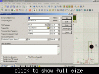
right click the microcontroller in proteus and choose Edit Properties. In the dialog select the program file for the micro. i.e., select the hex file click ok. then simulate.
 

In proteus when you will select hex file.
You also need to write processor clock frequency.Which is by default 1Mhz.
I simulate its a lcd base dc volt meter with battery charging cut relay.
It displays max dc 30volt.
And relay become off (unenergized) at 13.83v.
And relay become on again at 13.53v.
I think these volts should 12.5v for charging restore.

The relay turns off at 13.8 volts and turns on at 13.6 volts as you said, but because of the step size of potentiometer in proteus you are not able to see exact 13.6 and 13.8 volts. what is 12.5 v for charging restore?
 
Thank you....thanks a lot...by the way how can I replace this LCD with a seven segment display???...can we do it easily??

- - - Updated - - -

and if you don't mind I would like to know about how to change this voltage level???....how can I change this 13.6-13.8 to 12-12.4 or some level???
 

Thank you....thanks a lot...by the way how can I replace this LCD with a seven segment display???...can we do it easily??

I told you I haven't used & segment. Its not that difficult. You may get values like 1.2v ans 12.1v, so you should use 3 digit display with decimal points. decimal points may shift. you turn on /off the display using a transistor controlled by microcontroller. you can check examples in embedded-lab.com or check this link. http://extremeelectronics.co.in/mi...ent-displays-–-pic-microcontroller-tutorial/

There is no provision to change the value by hardware. you have to change that in code and then recompile the code.
 

Change the voltage values in the if else if statement and compile this code in mikroC. you have to set the right crystal frequency in mikroC and also in proteus.

Code:
// LCD module connections
sbit LCD_RS at RB0_bit;
sbit LCD_EN at RB1_bit;
sbit LCD_D4 at RB2_bit;
sbit LCD_D5 at RB3_bit;
sbit LCD_D6 at RB4_bit;
sbit LCD_D7 at RB5_bit;

sbit LCD_RS_Direction at TRISB0_bit;
sbit LCD_EN_Direction at TRISB1_bit;
sbit LCD_D4_Direction at TRISB2_bit;
sbit LCD_D5_Direction at TRISB3_bit;
sbit LCD_D6_Direction at TRISB4_bit;
sbit LCD_D7_Direction at TRISB5_bit;
// End LCD module connections

//Function Prototypes
void floattostring(double FP_NUM);

double FP_NUM, volt;
char string[6];

//Sub Function
void floattostring(double FP_NUM) {
        double fpnumber;
        long int befdec, aftdec;

        fpnumber = FP_NUM;

        befdec = fpnumber;                      // Fractional part is truncated
                                                // 12.163456 becomes 12
        aftdec = fpnumber * 100;            // 12.163456 becomes 1216
        aftdec = aftdec - (befdec * 100);   // 1216 - 1200 = 16


        if (fpnumber < 1) {
                string[0] = '0';
                string[1] = '.';
                string[2] = (aftdec/10) + 48;
                string[3] = (befdec/1)%10 + 48;
                string[4] = ' ';
                string[5] = '\0';

        }

        else if ((fpnumber >= 1) && (fpnumber < 10)) {
                string[0] = (befdec/1)%10 + 48;
                string[1] = '.';
                string[2] = (aftdec/10) + 48;
                string[3] = (befdec/1)%10 + 48;
                string[4] = ' ';
                string[5] = '\0';


        }

        else if ((fpnumber >= 10) && (fpnumber < 100)) {
                string[0] = (befdec/10) + 48;
                string[1] = (befdec/1)%10 + 48;
                string[2] = '.';
                string[3] = (aftdec/10) + 48;
                string[4] = (befdec/1)%10 + 48;
                string[5] = '\0';


        }

}

void main() {

       TRISA = 0b00000001;
       PORTA = 0b00000000;
       TRISB = 0b00000000;
       PORTB = 0b00000000;
       TRISC = 0b00000111;
       PORTC = 0b00000000;
       TRISD = 0b00000000;
       PORTD = 0b00000000;
       ADCON1 = 0b10001110;
       CMCON = 0b00000111;


       LCD_Init();
       Lcd_Cmd(_LCD_CURSOR_OFF);
       Lcd_Cmd(_LCD_CLEAR);
       Lcd_Out(1,1,"Voltage is");

       while(1) {
            volt = ADC_Read(0);
            volt = volt * 0.0305498981670061;
            volt = volt * 0.9612303748798462;
            floattostring(volt);
            Lcd_Out(2,1,string);
            Lcd_Out(2,7,"V");
            
            if(volt > 13.8) {      // Change value here
                   PORTD.F0 = 0;
                   
            }
            else if(volt < 13.6) {  // Change value here
                   PORTD.F0 = 1;
            }
            
       }


}
 
Thank you.its really working.......now the only pending requirement is the LCD to 7-segmant conversion..i am trying for that...thanks a lot internetuser2k12:)
 

Thank you.its really working.......now the only pending requirement is the LCD to 7-segmant conversion..i am trying for that...thanks a lot internetuser2k12:)

In 7 segment display you have to consider the decimal point. From microcontroller 7 lines go to the 7 segments and 1 for decimal point and 1 for enable/disable 7 segment.

Check these links http://www.microchip.com/forums/m436893-print.aspx

http://www.techshopbd.com/index.php/tutorial-categories/avr-tutorial/interfacing-7-segment-part-1
 
Last edited:

what is 12.5 v for charging restore?
Charging restore means,battery charger circuit resume charging.
During battery charge, charging control circuit also detects volts at battery terminals.
When these volts become 13.8 > 14.2,circuit stop charging to avoid battery from over charge.
Now battery starts self discharge and its volts decrease gradually.
At this stage we need to start charging again at 12.5v.
Now a days, new techniques are being used,like CC/CV,TRICKLE CHARGING etc.
Circuit does not stop charging completely,it change charging mode at 13.8 > 14.2v and drops charging rate near 200mA.
 
Last edited:

Thank you....,But I am really less experienced with programming...I know to write a program in C...but I don't know to write a C program for a PIC or other micro controller...I am always confused with this ports and everything....But I am trying to learn that.....so if I get a program for seven segment display really I don't know about how to add this program to the main program......can you suggest some website to learn the embedded c programming...???....I got something from this https://www.mikroe.com/products/view/11/book-pic-microcontrollers/,but its not enough...
 

while(1) {
volt = ADC_Read(0);
volt = volt * 0.0305498981670061;
volt = volt * 0.9612303748798462;
floattostring(volt);
Lcd_Out(2,1,string);
Lcd_Out(2,7,"V");

if(volt > 13.8) { // Change value here
PORTD.F0 = 0;

}
else if(volt < 13.6) { // Change value here
PORTD.F0 = 1;
} // end of while loop
}// end of main

How can we select next adc channel (AN1) if we need to show
an other analog value at PORTD.F1;
 
Last edited:

Change ADCON1 to 0b10001101; and also change volt = ADC_Read(0); to volt = ADC_Read(1);
 
  • Like
Reactions: pnjbtr

    pnjbtr

    Points: 2
    Helpful Answer Positive Rating
Just a suggestion:

In mikroC, now, you have 2 ADC functions you didn't have quite some time ago:
Code:
ADC_Init();
and
Code:
ADC_Get_Sample( );

You also have the old function:
Code:
ADC_Read( );

What ADC_Read does is, that, it initializes the ADC every time and triggers a reading. So, before every reading, all the initialization is done, although this isn't really necessary.

It may be better and faster to initialize the ADC once at the beginning, and then, only to take readings later.

Example:

Code:
unsigned int ADCR;
void main(void){
   ADC_Init();
   TRISA = 0xFF;
   while (1){
     ADCR = ADC_Get_Sample(0); //Number within parentheses is the channel to read from
     //............ Rest of the code
     //............
   }
}

Hope this helps.
Tahmid.
 

Change ADCON1 to 0b10001101; and also change volt = ADC_Read(0); to volt = ADC_Read(1);
I try to change code like this and build.
Although i got success.
But no effect in proteus.
Code:
              // LCD module connections
sbit LCD_RS at RB0_bit;
sbit LCD_EN at RB1_bit;
sbit LCD_D4 at RB2_bit;
sbit LCD_D5 at RB3_bit;
sbit LCD_D6 at RB4_bit;
sbit LCD_D7 at RB5_bit;

sbit LCD_RS_Direction at TRISB0_bit;
sbit LCD_EN_Direction at TRISB1_bit;
sbit LCD_D4_Direction at TRISB2_bit;
sbit LCD_D5_Direction at TRISB3_bit;
sbit LCD_D6_Direction at TRISB4_bit;
sbit LCD_D7_Direction at TRISB5_bit;
// End LCD module connections

//Function Prototypes
void floattostring(double FP_NUM);

double FP_NUM, volt;
char string[6];

//Sub Function
void floattostring(double FP_NUM) {
        double fpnumber;
        long int befdec, aftdec;

        fpnumber = FP_NUM;

        befdec = fpnumber;                      // Fractional part is truncated
                                                // 12.163456 becomes 12
        aftdec = fpnumber * 100;            // 12.163456 becomes 1216
        aftdec = aftdec - (befdec * 100);   // 1216 - 1200 = 16


        if (fpnumber < 1) {
                string[0] = '0';
                string[1] = '.';
                string[2] = (aftdec/10) + 48;
                string[3] = (befdec/1)%10 + 48;
                string[4] = ' ';
                string[5] = '\0';

        }

        else if ((fpnumber >= 1) && (fpnumber < 10)) {
                string[0] = (befdec/1)%10 + 48;
                string[1] = '.';
                string[2] = (aftdec/10) + 48;
                string[3] = (befdec/1)%10 + 48;
                string[4] = ' ';
                string[5] = '\0';


        }

        else if ((fpnumber >= 10) && (fpnumber < 100)) {
                string[0] = (befdec/10) + 48;
                string[1] = (befdec/1)%10 + 48;
                string[2] = '.';
                string[3] = (aftdec/10) + 48;
                string[4] = (befdec/1)%10 + 48;
                string[5] = '\0';


        }

}

void main() {

       TRISA = 0b00000001;
       PORTA = 0b00000000;
       TRISB = 0b00000000;
       PORTB = 0b00000000;
       TRISC = 0b00000111;
       PORTC = 0b00000000;
       TRISD = 0b00000000;
       PORTD = 0b00000000;
       ADCON1 = 0b10001110;
       CMCON = 0b00000111;


       LCD_Init();
       Lcd_Cmd(_LCD_CURSOR_OFF);
       Lcd_Cmd(_LCD_CLEAR);
       Lcd_Out(1,1,"Voltage is");

       while(1) {
            volt = ADC_Read(0);
            volt = volt * 0.0305498981670061;
            volt = volt * 0.9612303748798462;
            floattostring(volt);
            Lcd_Out(2,1,string);
            Lcd_Out(2,7,"V");

            if(volt > 13.8) {      // Change value here
                   PORTD.F0 = 0;

            }
            else if(volt < 13.6) {  // Change value here
                   PORTD.F0 = 1;
            }


          ADCON1 = 0b10001101;        //next 2nd channel selection
          
          volt = ADC_Read(1);         //AN1 will also read an other  analog value
          
            if(volt > 15.8) {      // Change value here
                   PORTD.F1 = 0;

            }
            else if(volt < 14.6) {  // Change value here
                   PORTD.F1 = 1;
            }
          
          
       }


}
 

Try this code. You have to make TRISA = 0b00000011;


Code:
// LCD module connections
sbit LCD_RS at RB0_bit;
sbit LCD_EN at RB1_bit;
sbit LCD_D4 at RB2_bit;
sbit LCD_D5 at RB3_bit;
sbit LCD_D6 at RB4_bit;
sbit LCD_D7 at RB5_bit;

sbit LCD_RS_Direction at TRISB0_bit;
sbit LCD_EN_Direction at TRISB1_bit;
sbit LCD_D4_Direction at TRISB2_bit;
sbit LCD_D5_Direction at TRISB3_bit;
sbit LCD_D6_Direction at TRISB4_bit;
sbit LCD_D7_Direction at TRISB5_bit;
// End LCD module connections

//Function Prototypes
void floattostring(double FP_NUM);

double FP_NUM, volt, volt1;
char string[6];

//Sub Function
void floattostring(double FP_NUM) {
        double fpnumber;
        long int befdec, aftdec;

        fpnumber = FP_NUM;

        befdec = fpnumber;                      // Fractional part is truncated
                                                // 12.163456 becomes 12
        aftdec = fpnumber * 100;            // 12.163456 becomes 1216
        aftdec = aftdec - (befdec * 100);   // 1216 - 1200 = 16


        if (fpnumber < 1) {
                string[0] = '0';
                string[1] = '.';
                string[2] = (aftdec/10) + 48;
                string[3] = (befdec/1)%10 + 48;
                string[4] = ' ';
                string[5] = '\0';

        }

        else if ((fpnumber >= 1) && (fpnumber < 10)) {
                string[0] = (befdec/1)%10 + 48;
                string[1] = '.';
                string[2] = (aftdec/10) + 48;
                string[3] = (befdec/1)%10 + 48;
                string[4] = ' ';
                string[5] = '\0';


        }

        else if ((fpnumber >= 10) && (fpnumber < 100)) {
                string[0] = (befdec/10) + 48;
                string[1] = (befdec/1)%10 + 48;
                string[2] = '.';
                string[3] = (aftdec/10) + 48;
                string[4] = (befdec/1)%10 + 48;
                string[5] = '\0';


        }

}

void main() {

       TRISA = 0b00000011;
       PORTA = 0b00000000;
       TRISB = 0b00000000;
       PORTB = 0b00000000;
       TRISC = 0b00000111;
       PORTC = 0b00000000;
       TRISD = 0b00000000;
       PORTD = 0b00000000;
       ADCON1 = 0b10001110;
       CMCON = 0b00000111;


       LCD_Init();
       Lcd_Cmd(_LCD_CURSOR_OFF);
       Lcd_Cmd(_LCD_CLEAR);
       Lcd_Out(1,1,"Voltage is");
       ADC_Init();

       while(1) {
            volt = ADC_Read(0);
            volt = volt * 0.0305498981670061;
            volt = volt * 0.9612303748798462;
            floattostring(volt);
            Lcd_Out(2,1,string);
            Lcd_Out(2,7,"V");

            if(volt > 13.8) {      // Change value here
                   PORTD.F0 = 0;

            }
            else if(volt < 13.6) {  // Change value here
                   PORTD.F0 = 1;
            }


          ADCON1 = 0b10001101;        //next 2nd channel selection
          
          volt1 = ADC_Read(1);         //AN1 will also read an other  analog value
          
            if(volt1 > 15.8) {      // Change value here
                   PORTD.F1 = 0;

            }
            else if(volt1 < 14.6) {  // Change value here
                   PORTD.F1 = 1;
            }
          
          
       }


}
 

Status
Not open for further replies.

Similar threads

Part and Inventory Search

Welcome to EDABoard.com

Sponsor

Back
Top