Continue to Site

Welcome to EDAboard.com

Welcome to our site! EDAboard.com is an international Electronics Discussion Forum focused on EDA software, circuits, schematics, books, theory, papers, asic, pld, 8051, DSP, Network, RF, Analog Design, PCB, Service Manuals... and a whole lot more! To participate you need to register. Registration is free. Click here to register now.

LC Low pass filter design for SPWM filtering

Status
Not open for further replies.
the full cycle period is 50HZ...
L=8.8H
The inductor is much too big. If you connect a load (even a light bulb) to the output, the voltage will drop and the current will be very low. I think L should be about 100 times smaller.

Cut off frequency..F_(cutoff frequency)=1/(2π √LC)...........
Cut off frequency should be much higher than 50Hz. If the PWM frequency is 5KHz, then the cut off frequency could be about 500Hz.

L=100mH, C=1uF may be good values. The inductor can also be smaller. If you choose L=10mH, then C=10uF.
 
Hi Longcrystal
As you probably know best situation for an LC butter worth 2nd order filter is where zeta is one ( RO=0.5sqrt(L/C) ) . so you can easily calculate numbers according this formula and determine a parameter to normalize values . if it is not clear to you , tell me , please , then i can write some pages for you as an example !
Best Wishes
Goldsmith


hi goldsmith thank for u replied and kindly helpful guide....actually butter worth filter had study before...but last time i was study in op-amp case...long time ago ...a bit forget must be revision...but for my project .. i didnt use any op-amp to achieve the target ... so i still can use butterworth concept to apply in this case???

May i ask a very stupid question ...if i want reduce my inductance value for my case...... may i ask some basic question ...what is the carrier frequency ....is the mean ??? SPWM i controlled in 50Hz or 4KHz in the digital pulse is mean for the carrier frequency ??????? and if i change for my situation ..last time i was design the spwm pulse in 50Hz period to generate sine wave....and the inductor value is 10H....it is quite big problem....if i want to reduce the inductance could i adjust my spwm pulse into 4KHz ??? and for my basic calculation ...can i substitution like that??


4kHz= 1/(2π√((L)(1000nF)))
16000x10^3 Hz=(1/(2π√((L)(1000nF))))^2
L=1.583 mH

like this case i reduce a lot inductance seem from 50Hz=10H and 4KHz=1.583mH............................and just wondering if i choose( L and C) 1.583mH and C=1000nF .................really can achieve my output on 50Hz....???? because seem like equation not pointing for 50Hz......sorry i was thinking too much ...........ya goldsmith please write some example for me .....related with SPWM PULSE in different pulse frequency 50 to 4KHz ...just make three or Two case example...to achieve the sine wave 50Hz .......i will revision back for my butterworth and Low Pass filter book too....really big thank for u kindly help...maybe recently i will keep asking the question for u ....it is convenience for u reply ???? i really willing to learn anything.......thank for give u more information ~~~~

- - - Updated - - -

- - - Updated - - -

in the simulation....if i adjusted like this value ...the waveform for the sine wave and digital pulse ...become very weird shape .....i havent try in real life...because for my case ...i dont have inductor in the hand ...so want to calculate very possible ..answer...then i will make a order to buy the inductor....or make the inductor by myself....but donthave knowledge for make inductor ............ but i will keep on the solve this problem as well...

- - - Updated - - -

Cut off frequency should be much higher than 50Hz. If the PWM frequency is 5KHz, then the cut off frequency could be about 500Hz.


if my spwm is 4KHz .... how do i know my cut off frequency is how many ???? maybe got other formula ...can solve this ??? can u show me an example ... i would like to know also ~~~~big thank ^^~~~~ the inductor can smaller.... in the software have try to adjust Capacitor value and Inductor value ..it would very sensitive no getting shape wave and easy to compile error too...but i will test in real life also......but the inductor is the big problem..... for capacitor it would be fine .....thank for u guide ...i wait for u reply too...

..
 

Hi again
Carrier frequency word came from an old way to create SPWM ( comparison between message signal ( sine wave ) and a higher frequency triangle wave ) that triangle wave called carrier signal . but if you are using a MCU to create SPWM , you should measure frequency of original square wave , and then it is your carrier frequency , message signal just control variations of D.C of your square wave .
And an advise : if you increase frequency of carrier ( for example something near 15 KHZ ) and then if your message signal be something like a 50 HZ sine wave , if you see spectrum of your SPWM , you will see you have HF side bands and your message signal . lowest frequency in this spectrum is your message signal . so if you use an LPF , it will remove HF side bands as well . but because your lowest frequency is 50 HZ , you can choose your filter for 5KHZ or perhaps 8 KHZ . thus high frequency components can't go through out put , but 50 HZ can go ! a pure sine wave !
Best Wishes
Goldsmith
 

goldsmith : thank for clearly describe for the Carrier Frequency.. and now i know that in old way is generate triangle wave.. in MCU i generate the Square wave spwm ((own decided (2KHz to 4KHz)).....and more question want to ask...... u said that ((can choose your filter for 5KHZ or perhaps 8 KHZ .... thus high frequency components can't go through out put , but 50 HZ can go ! a pure sine wave !) ) <-- mean that the low pass filter is form as LC circuit ?? and the LC circuit will automatically cut in 50Hz??? ....and if i choose F carrier= 4kHz..................

then 4KHz= 1/(2π√((L)(1000nF))) ... 16000x10^3 Hz=(1/(2π√((L)(1000nF))))^2/////L=1.583 mH ... then this equation mean i can adjust my L and C ..and decide what value of L and C should be put ??? ,,,,,,,,,and may i ask in LC circuit....automatically will be generate 50Hz ??...depend my L and C choosing right ? and direct use F_(cutoff frequency)=1/(2π √LC).???? and in the equation is Variable of Fc ..mean is cut off.....so if i want play the substitution,,,,, can i replace the cut off = carrier to calculate it ??? or need adjust both L and C ....to achieve direct cut off 50Hz mean

.sorry for my confused sentence.

- - - Updated - - -

godfreyl ; hi godfrey thank for reply my question actually wanna ask (Cut off frequency should be much higher than 50Hz. If the PWM frequency is 5KHz, then the cut off frequency could be about 500Hz. L=100mH, C=1uF may be good values. The inductor can also be smaller. If you choose L=10mH, then C=10uF.)

ok well .... if example 5KHz... ... as u said cut off must be greater than 50Hz........ and why cut off frequency is 500Hz ??? and my purpose is generate sine wave 50Hz .....and this out of range for my value .... just wanna ask more~~~wait u for u reply thankq ^^
 

Hi again
at first , don't confuse yourself ! an LPF will conduct from zero hertz until it's cut off frequency . your cut off is 8 KHZ , but you don't have 8 KHZ you have 15 KHZ ! hence it can't eliminate 50 HZ , and it will go through out put !
( increase your SPWM carrier up to 15 KHZ . and about calculations of your filter , it is completely wrong ! your formula is not accepted fro this aim ! it needs some other things too .


L=100mH, C=1uF
And i think these values are like a big joke !

Best Wishes
Goldsmith
 

Code:
about calculations of your filter , it is completely wrong ! your formula is not accepted fro this aim ! it needs some other things too .
I see, that you sugested 4 KHz LPF cut-off for 8 kHz PWM in post #2. But you didn't tell now where you see the fault with the 1.6 mH/1µF calculation.

My suggestion would be to take a look at acceptable L values based on the inductive voltage drop first. 10 mH, as discussed by godfreyl corresponds e.g. to 7% at 5A, looks good. Intended PWM frequency attenuation is the other interesting parameter.

And i think these values are like a big joke !
I tend to agree for 100 mH, at least in case of a 5A inverter.
 

Although a formula can tell us what center frequency will result from which coil and which capacitor...

We also must factor in the amount of current, to determine what henry value is suitable, and what uF value:

To illustrate:

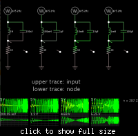
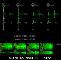
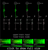
Four combinations of LC tanks to obtain 500 Hz.

Series resistor 30 ohms.


Series resistor 300 ohms.


As we can see, the LC combinations vary in their ability to pass current. This is indicated by differing volt levels on the series resistors.

Also notice the different shapes of the filter curves.

Scope sweeps are from 20 to 1000 Hz.

I will post results for series LC filters, just in case that's what is being used.

- - - Updated - - -

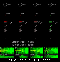
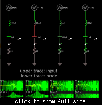
Four combinations of LC series to obtain 500 Hz.

Series resistor 1 ohm.


Series resistor 10 ohms.


Again notice the LC combinations vary in their ability to pass current. This is indicated by differing volt levels on the series resistors.

Also notice the different shapes of the filter curves.

Scope sweeps are from 20 to 1000 Hz.
 

To illustrate:

Four combinations of LC tanks to obtain 500 Hz.
Although we get some insights about Q effect, a low pass filter simulation would be more interesting for the present problem.

As side remark, by performing a simulation as sweep in time domain, you get specific transient effects, as observable in the high Q band stop case.
 
Last edited:

What values do you suggest?
DOn't forget that those LC filters , will have variations in gain , if your load is improper . the best situation is area of zeta = 1 . so , the out put will need a feed back ( DC feed back loop ) to improve the effect , but if your RL be higher than normalized impedance the out put voltage can be increase up to some kilo volts ! that filter has an special out put impedance , which will given with formula of 0.5sqrt(L/C) .
With those values ( 100 and 1 u ) it will be around 150 ohms ! which is not proper . first of all you should consider , your maximum and minimum load and effect of feed back path , to have stable out put sine wave . ( i'm talking regarding it's amplitude ) .
Best Wishes
Goldsmith
 

Although we get some insights about Q effect, a low pass filter simulation would be more interesting for the present problem.

Yes. After several posts I lost track whether the discussion had changed to LC as referring to a resonant configuration.

Here are my simulation results for a second order LC low pass filter.

As before, the values increase or decrease in steps of 10x.


The resistors are 1 ohm so that current over 4 amps can flow, if possible. These are not necessarily the values that will be used in the inverter.


The layouts do not permit the same current to flow. The middle two layouts have values that allow 4 A or more to flow.

However their rolloff curves are not as steep as the other two. I'm not sure how to account for this.

It's possible there are intermediate values between the middle two layouts, which will allow slightly greater current flow.

As side remark, by performing a simulation as sweep in time domain, you get specific transient effects, as observable in the high Q band stop case.

Yes, I suppose you mean the lumps in the waveforms after the resonant frequency. I often see those when doing frequency sweeps.

At first I thought it showed how accurate the simulator is.

But then I saw that the lumps always appeared AFTER sweeping past the resonant frequency, and they occured in either direction, both when sweeping up AND when sweeping downward.

This means the filter response is 'bouncing around' incorrectly, after the extreme changes near resonant frequency.

It means that I should slow down the sweep, to eliminate the false transients.
 

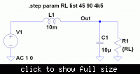
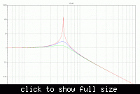
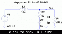
As previous said, 10 mH/10 uF doesn't look bad for 5 A output current. The magnitude curve is plotted for 1 %, 50% and 100 % resistive load. Although there's a huge peaking of the unloaded filter at 500 Hz, the filter transmission at 50 Hz and the assumed PWM frequency of 8 kHz isn't affected. A nonlinear load, e.g. a non-PFC power supply may still show unwanted effects.


Hi again
at first , don't confuse yourself ! an LPF will conduct from zero hertz until it's cut off frequency . your cut off is 8 KHZ , but you don't have 8 KHZ you have 15 KHZ ! hence it can't eliminate 50 HZ , and it will go through out put !
( increase your SPWM carrier up to 15 KHZ . and about calculations of your filter , it is completely wrong ! your formula is not accepted fro this aim ! it needs some other things too .


And i think these values are like a big joke !

Best Wishes
Goldsmith

(it needs some other things too ) any method ...????

goldsmith ...if my carrier frequency is spwm pulse in dc square wave for spwm one cycle 1kHz to 5Khz ...depend for my setting........how dp i oscillate ac sine wave exactly in 50Hz output...and how do i predict from spwm pulse waveform generate to sine wave waveform......... any calculation can excatly know after LC will change the shape become sine wave.....
 
Last edited:

DOn't forget that those LC filters , will have variations in gain , if your load is improper .
[snip useless information.]
Best Wishes
Goldsmith
You like to tell other people that they are are stupid, their calculations are wrong, and their designs won't work, but you don't help by giving useful information.

I asked a very specific, very simple question: "What values do you suggest?". You have not answered that question. Do you not want to help longcrystal?
 
Last edited:

You like to tell other people that they are are stupid, their calculations are wrong, and their designs won't work, but you don't help by giving useful information.
WHo told that i'm thinking that they are stupid ? you are here from this year but i'm here from 2010 and it is my first time to hear this ! why most of the times your words are impolite and hateful ? i don't know !
Yes i have answered the question and how to calculate . but as it appears you don't know any thing regarding impedance of a butter worth filter and of course any thing about an inverter .
 

Yes i have answered the question and how to calculate .
You did not answer the question. You gave no values. You did not explain how to calculate. longcrystal is still asking how to do the calculation.
 

I gave the way ! not the answer ! i told how to find answer !
Again : normalize the impedance with value of the zeta = 1 and then improve the values according to the normalized impedance and then recalculate the impedance ! and then affect , effect of DC feed back loop . is that unclear ? can't you really understand it ?
 

it appears you don't know any thing regarding impedance of a butter worth filter and of course any thing about an inverter .
You are right, I don't know much about inverters. I know what a Butterworth filter is but I have never heard of a "butter worth filter". It must be different to a Butterworth filter if this is true:
...best situation for an LC butter worth 2nd order filter is where zeta is one ( RO=0.5sqrt(L/C) ) .
 

Status
Not open for further replies.

Similar threads

Part and Inventory Search

Welcome to EDABoard.com

Sponsor

Back
Top