yefj
Advanced Member level 5

- Joined
- Sep 12, 2019
- Messages
- 1,557
- Helped
- 1
- Reputation
- 2
- Reaction score
- 5
- Trophy points
- 38
- Activity points
- 9,377
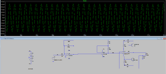
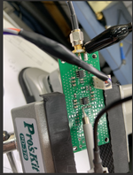
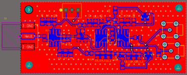
Hello , I have implemented a PCB based on the attached simulation file in the RAR and photo.
I have used ceramic capacitors of 100nF 1uF and 10uF for decoupling.
I tried to put vias on the ground plane to reduce noised.
photos description shown below.
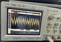
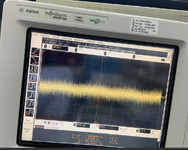
based on the implementation how do you asses the noise level i got ? where could i improve to get a better result then photo 11.PNG zoomed?
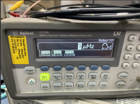
Maybe my input signal (11.PNG) is too noisy?
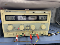
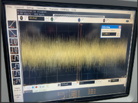
maybe my power supply 7.5V is noisy and the decoupling is not working? (photo 13.PNG)
I only tested the first two stages ,What could be done to improve the result noisewise?
Thanks.
11.PNG is the input signal i get from the signal generator( I tried to simulate both on pure 1mv dc and sine 10mV pk-pk)
7.png LSPICE simulation
12.png : PCB TEST point of the output
13 .PNG: voltage singal of the input 7.5V from the power supply
q14.png PCB implementation of the schematics
physical_photos.zip: photos of the ceramic capacitors being used for decoupling.
Attachments
Last edited by a moderator:
