Continue to Site

Welcome to EDAboard.com

Welcome to our site! EDAboard.com is an international Electronics Discussion Forum focused on EDA software, circuits, schematics, books, theory, papers, asic, pld, 8051, DSP, Network, RF, Analog Design, PCB, Service Manuals... and a whole lot more! To participate you need to register. Registration is free. Click here to register now.

How to interface BP Transducer to PIC18F?

Status
Not open for further replies.

baileychic

Advanced Member level 3
Joined
Aug 2, 2017
Messages
728
Helped
56
Reputation
112
Reaction score
57
Trophy points
28
Activity points
7,033
How to interface BP Transducer to PIC16F?

I need to use these and interface BP transducer and Analog Stimulator to PIC16F Mic rocontroller.

BP transducer needs to connect to PIC16F ADC input and Analog Stimulator needs to connect to DAC output of PIC18F.

I will be using PIC16F1779 which has both 10-bit ADC and DAC.

Find attached file.

This is for a lab experiment.

Also fins attached flowchart.
 

Attachments

  • _model_2200.pdf
    832.2 KB · Views: 145
  • bp amp.pdf
    786.4 KB · Views: 136
  • bp transducer.pdf
    104.4 KB · Views: 129
  • Fowchart.pdf
    38.8 KB · Views: 121

Do you want to use the pressure transducer with its dedicated amplifier, or include the amplifier function in your design? In the latter case, does your design need to provide fully galvanic isolation like the shown bp amp?

The stimulation waveform generation and respective control algorithms are apparently beyond the scope of this thread. Nevertheless they have to be designed by someone and compiled into the PIC.
 

I will try both methods that are:

1. Using a dedicated amplifier and
2. Custom amplifier

I want to implement Galvanic isolation if required.

Regarding the algorithm, the student said that ADC needs to be used to read the sensor and the vale should be sent to DAC to get a voltage and amplified if required and fed into Stimulator.
Is there a requirement of a special algorithm?
 

I can't read a sense into sending the blood pressure signal to stimulation amplifier. What should be the purpose?
 
@FvM

The student had only given nformation that ADC reads the sensor/transducer and the raw ADC value will be scaled and converted to suitable voltage using internal DAC of PIC and DAC output voltage is given to Stimulator.

If more information is needed then please tell what are the requirements and I will ask the Student and will update.

- - - Updated - - -

@FvM

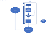
This is the Flowchart that the Student's Professor has given. She (I) have to implement it using PIC?
Show what is the method?

Just read the transducer using ADC and then scale the raw ADC value and feed it to get DAC output voltage and then use an OpAmp to get the required stimulus voltage for Analog Stimulator?
 

Attachments

  • Fowchart_Final.png
    Fowchart_Final.png
    20.4 KB · Views: 135

I don't understand the exact purpose of the stimulator part, but I really don't need to know. You should however understand it if you are doing any srious support work for the project.

There should be a detailed experiment description supplementing the "flowchart". Without it, one might guess that the student neither understands the project purpose.
 

I will give a detailed report to the student (the student has only provided me the PDFs which I have attached in this thread).

I just want to know whether I can use a 5V excitation voltage for the transducer/sensor same as PICs power supply and read the sensor using ADC and feed the 10-bit ADC result to internal DAC of PIC and get a DAC output voltage and then amplify it if needed using an OpAmp (MCP6001) and feed it to Analog Stimulator?

I have to design the PIC interface circuit for the BP transducer and Analog Stimulator to conduct the experiment.

Should I use an Instrumentation Amplifier to get the stimulator voltage?
 

Re: How to interface BP Transducer to PIC16F?

@FvM

I guess the setup should be like this:

Provide say 5V excitation voltage to transducer/sensor.
Put an OpAmp between transducer output and PIC's ADC input
Read transducer output using ADC and get the raw ADC value of 10-bit
Scale this reading if required for the internal DAC of PIC
Then feed the DAC output to Analog Stimulator
Analog Stimulator output is connected to the transducer for control

What do you say?

The professor needs solution for both methods that are using the BP Amp instrument and also external OpAmp.

So, If the above method is correct then I will use the chosen PIC's internal OpAmp to amplify the transducer's output for ADC.

Note: I have never used these instruments and this also applies for the student.


This is what is mentioned in the transducer's datasheet.

Operating range: –50 to +300 mmHg
Excitation voltage: 2 to 10 V DC
Sensitivity (full range): 5 µV/V/mmHg

So, If my excitation voltage is 5V DC then I get

5uV * 5 = 25uV for 5V and it is equal to 1 mmHg?

If yes, then range is -50 to 300 mmHg = 350

So, 25uV * 350 = 8750 uV = 8.75mV?

So, I need to amplify this value to 5V for ADC input?
 
Last edited:

Hi,

Operating range: –50 to +300 mmHg
Excitation voltage: 2 to 10 V DC
Sensitivity (full range): 5 µV/V/mmHg

So, If my excitation voltage is 5V DC then I get

5uV * 5 = 25uV for 5V and it is equal to 1 mmHg?

If yes, then range is -50 to 300 mmHg = 350

So, 25uV * 350 = 8750 uV = 8.75mV?

So, I need to amplify this value to 5V for ADC input?

If you take the units correctly with your calculations:

5uV/V/mmHg * 5V = 25uV/mmHg

25uV/mmHg * 350mmHg = 8750 uV = 8.75mV

While these calculations are basically correct...In reality I'd expect problems because of:
* output offset of the sensor
* gain variation of the sensor
* reference voltage error
* amplifier gain and offset error
* no headrom to be able to detect "out of range"

At this stage it's time to consider about
* the measurement method: absolute or ratiometric
* schematic
* error calculations

Klaus
 

Human BP doesn't exceed 250 mmHg and transducer can measure up to 300 mmHg. So, will there be an out of range reading?
 

Hi,

I didn´t go through the datasheets, thus I don´t know about the sensor errors...

So it´s just a reminder to consider worst case scenarios not to get in trouble later...

Klaus
 

The student discussed with the professor and the new requirement is as below.

The BP transducer gives voltage output and also can connect to BP AMP I2C Input. BP AMP also gives direct mmHg data at its I2C output connector but the professor doesn't want to use it.
He wants the student to use the voltage output of the BP sensor (transducer) and use ADC of MCU and convert it into a voltage level between 0 and 10V and a pulse of 20 Hz to 100 Hz that is single output to input into stimulator.

The pulse voltage level should be between 0 and 10V and 20 Hz to 100 Hz based on sensor (ADC) value.

How can this be achieved using PIC16F1779?

I can use a DAC to get a voltage and a digital output pin to get pulse output but need to get both on one pin.

I can use additional transistors, N-Mosfet, OpAmps with PIC if required to get the required output.

- - - Updated - - -

Can I use PIC16F1779's internal DAC to get the pulse output signal that is:

I will update the DAC value in Timer ISR which can give 20 Hz to 100 Hz max 5V output pulse and I will use an external OPAMP with +10V supply for it to get the amplified pulse output which can vary between 20 Hz to 100 Hz with voltage level 10V max.

Will this work?

If it works then I am thinking about using ti.com OPA743 (12V rail-to-rail opamp).
 

My hardware setup will be like this.

I will not be using BP AMP and BP STIMULATOR.

I will be using just BP sensor (Professor's requirement to use just that)
The BP sensor is connected to internal OPAMP of PIC16F1779 and OPAMP's output is fed to ADC input.
ADC reading is taken and converted to DAC value and based on the DAC value (or ADC value) then timer interrupt period is selected between 20 Hz to 100 Hz.
The DAC will output a pulsed DC between 0-5V and 20 Hz to 100 Hz.
This is amplified to 20V max pulsed using external 36V Rail-to-Rail OPAMP.
The external OPAMP acts as the stimulator.

So, How should I write the c code that is to get Systolic and Diastolic BP readings in mmHg for displaying on LCD?
 

Attachments

  • 2019-05-04_11-42-00.png
    2019-05-04_11-42-00.png
    139.3 KB · Views: 129
  • 2019-05-04_11-42-30.png
    2019-05-04_11-42-30.png
    140.4 KB · Views: 121

I have a new issue related to this project.

The BP sensor gives a reading 0 to 2.5V max for 0 to 250 mmHg BP. I am using PIC16F1779 with ADC+Internal OPAMP1+DAC+Internal OPAMP3+Stimulator out with external OPAMP circuits.

The 0 to 2.5V from the sensor is fed to OPAMP1's (Internal to PIC) IN+ pin and IN- pin has two gain resistors Ri and Rf of 10k each which amplifies this signal to 0 to 5V range.
The 10 - bit ADC value is directly fed to DAC (at present) and Timer1 and Timer3 are used to generate pulses out of DAC output (0 to 2.5V sensor voltage = 0 to 60 mmHg = -18V to +18V, 20 Hz to 100 Hz, 2000us to 100us pulse width). This is working fine.

The DAC out is buffered with UG OPAMP using PIC's Internal OPAMP3.

Stimulator out pulse is Bi-Polar and it is applied to the subject (human or animal).

Now, I need to calculate the MAP (Mean Arterial Pressure from BP readings that is Systolic and Diastolic).

This is the equation.

MAP= 1/3*sbp+2/3*dbp

or

MAP=DBP+1/3(SBP-DBP)

SBP = Systolic BP and DSP = Diastolic BP.

For now, I am just reading ADC (sensor) continuously in ADC interrupt and taking the peak value.

I want to get both SBP and DBP readings from ADC. How should I read the sensor? PIC is running at 8 MHz clock. Can't change this.

If needed, I can post the current code.

If the blood pressure falls below 60 mmHg then stimulator applies the corresponding to nerve of the subject from above skin.


This is the Stimlator circuit that I have designed. 0 to 5V (Buffered) from DAC+OPAMP3 is fed to this circuit.

Also attached PSU circuit that I have designed.

I need minimum +/- 2V to max +/-18V stimulator output for 0 to 60 mmHg BP.

How to read SBP and DBP?

Here is the present code.


Code C - [expand]
1
2
3
4
5
6
7
8
9
10
11
12
13
14
15
16
17
18
19
20
21
22
23
24
25
26
27
28
29
30
31
32
33
34
35
36
37
38
39
40
41
42
43
44
45
46
47
48
49
50
51
52
53
54
55
56
57
58
59
60
61
62
63
64
65
66
67
68
69
70
71
72
73
74
75
76
77
78
79
80
81
82
83
84
85
86
87
88
89
90
91
92
93
94
95
96
97
98
99
100
101
102
103
104
105
106
107
108
109
110
111
112
113
114
115
116
117
118
119
120
121
122
123
124
125
126
127
128
129
130
131
132
133
134
135
136
137
138
139
140
141
142
143
144
145
146
147
148
149
150
151
152
153
154
155
156
157
158
159
160
161
162
163
164
165
166
167
168
169
170
171
172
173
174
175
176
177
178
179
180
181
182
183
184
185
186
187
188
189
190
191
192
193
194
195
196
197
198
199
200
201
202
203
204
205
206
207
208
209
210
211
212
213
214
215
216
217
218
219
220
221
222
223
224
225
226
227
228
229
230
231
232
233
234
235
236
237
238
239
240
241
242
243
244
245
246
247
248
249
250
251
252
253
254
255
256
257
258
259
260
261
262
263
264
265
266
267
268
269
270
271
272
273
274
275
276
277
278
279
280
281
282
283
284
285
286
287
288
289
290
291
292
293
294
295
296
297
298
299
300
301
302
303
304
305
306
307
308
309
310
311
312
313
314
315
316
317
318
319
320
321
322
323
324
325
326
// LCD module connections
sbit LCD_RS at LATB4_bit;
sbit LCD_EN at LATB5_bit;
sbit LCD_D4 at LATB0_bit;
sbit LCD_D5 at LATB1_bit;
sbit LCD_D6 at LATB2_bit;
sbit LCD_D7 at LATB3_bit;
 
sbit LCD_RS_Direction at TRISB4_bit;
sbit LCD_EN_Direction at TRISB5_bit;
sbit LCD_D4_Direction at TRISB0_bit;
sbit LCD_D5_Direction at TRISB1_bit;
sbit LCD_D6_Direction at TRISB2_bit;
sbit LCD_D7_Direction at TRISB3_bit;
// End LCD module connections
 
sbit Read_Blood_Pressure_Switch at RC0_bit;
sbit Read_Blood_Pressure_Switch_Direction at TRISC0_bit;
 
sbit GO_DONE_bit at ADCON0.B1;
 
//#define BASIC_TEST
 
#ifndef BASIC_TEST
    #define FULL_TEST
#endif
 
#define Blood_Pressure_Threshold        246.00
 
#define Max_BP_Transducer_Output_Voltage  2.50
#define Max_OpAmp_Output_Voltage          5.00
#define Max_BP_Reading_In_mmHg          250.00
 
#define ADC_Resolution 1023.0
#define DAC_Resolution 1023.0
 
typedef struct {
  unsigned int rawAdcValue;
  unsigned int oldRawAdcValue;
  double bpValueInMmHg;
  double bpTransducerOutputVoltage;
  unsigned int maxAdcReading;
  unsigned int oldMaxAdcReading;
}ADC_TYPE;
 
typedef struct {
  unsigned int dacValue;
}DAC_TYPE;
 
typedef struct {
  unsigned int timer1ReloadValue;
  unsigned int oldTimer1ReloadValue;
}TIMER1_TYPE;
 
typedef struct {
  unsigned int timer3ReloadValue;
  unsigned int oldTimer2ReloadValue;
}TIMER3_TYPE;
 
typedef struct {
  ADC_TYPE adc;
  DAC_TYPE dac;
  TIMER1_TYPE timer1;
  TIMER3_TYPE timer3;
}BLOOD_PRESSURE_MONITOR_TYPE;
 
BLOOD_PRESSURE_MONITOR_TYPE bpMonitor;
unsigned char flagReg = 0;
char txt[23];
 
sbit readBloodPressure at flagReg.B0;
sbit toggleDacOutput   at flagReg.B1;
 
const code char txt1[] = "   BP Monitor   ";
const code char txt2[] = "BP: ";
const code char txt3[] = "SV: ";
 
//Timer1
//Prescaler 1:1; TMR1 Preload = 55536; Actual Interrupt Time : 5 ms
void InitTimer1() {
    T1CON = 0x00;
    TMR1IF_bit = 0;
    TMR1H = 0x00;
    TMR1L = 0x00;
    TMR1IE_bit = 1;
}
 
//Timer3
//Prescaler 1:1; TMR3 Preload = 65336; Actual Interrupt Time : 100 us
void InitTimer3() {
    T3CON = 0x00;
    TMR3IF_bit = 0;
    TMR3H = 0xFF;
    TMR3L = 0x38;
    TMR3IE_bit = 1;
}
 
long map(long x, long in_min, long in_max, long out_min, long out_max) {
    return (x - in_min) * (out_max - out_min) / (in_max - in_min) + out_min;
}
 
void interrupt() {
    if((ADIE_bit) && (ADIF_bit)) {
        ADIF_bit = 0;
 
        bpMonitor.adc.rawAdcValue = (unsigned int)(ADRESH << 8) + ADRESL;
 
        if(bpMonitor.adc.oldMaxAdcReading < bpMonitor.adc.rawAdcValue) {
           bpMonitor.adc.oldMaxAdcReading = bpMonitor.adc.rawAdcValue;
        }
 
        if(bpMonitor.adc.rawAdcValue <= Blood_Pressure_Threshold) {
            if(toggleDacOutput == 0) {
                bpMonitor.dac.dacValue = (unsigned int)map((long)bpMonitor.adc.rawAdcValue, 0, 246, 1023, 0);
                bpMonitor.timer1.timer1ReloadValue = (unsigned int)map((long)bpMonitor.adc.rawAdcValue, 0, 246, 15536, 55536);
                bpMonitor.timer3.timer3ReloadValue = (unsigned int)map((long)bpMonitor.adc.rawAdcValue, 0, 246, 61536, 65336);
            }
 
            if(bpMonitor.timer1.timer1ReloadValue != bpMonitor.timer1.oldTimer1ReloadValue) {
                bpMonitor.timer1.oldTimer1ReloadValue = bpMonitor.timer1.timer1ReloadValue;
                if(TMR1ON_bit == 0) { TMR1H = 0xFE; TMR1L = 0xFF; TMR1ON_bit = 1; }
            }
        }
    }
 
    if((TMR1IE_bit) && (TMR1IF_bit)) {
        TMR1IF_bit = 0;
        TMR1H = bpMonitor.timer1.timer1ReloadValue >> 8;
        TMR1L = bpMonitor.timer1.timer1ReloadValue;
 
        toggleDacOutput = ~toggleDacOutput;
 
        if(toggleDacOutput) {
           DAC1REFH = bpMonitor.dac.dacValue >> 8;
           DAC1REFL = bpMonitor.dac.dacValue;
 
           TMR3H = bpMonitor.timer3.timer3ReloadValue >> 8;
           TMR3L = bpMonitor.timer3.timer3ReloadValue;
 
           DAC1LD_bit = 1;
           TMR3ON_bit = 1;
        }
        
        GO_DONE_bit = 1;
    }
 
    if((TMR3IE_bit) && (TMR3IF_bit)) {
        TMR3IF_bit = 0;
        TMR3ON_bit = 0;
 
        DAC1REFH = 0;
        DAC1REFL = 0;
        DAC1LD_bit = 1;
    }
}
 
// copy const to ram string
char *CopyConst2Ram(char *dest, const code char *src) {
    char *d;
 
    d = dest;
 
    for(;*dest++ = *src++;);
 
    return d;
}
 
void initailizePorts() {
    TRISA = 0x37;
    TRISB = 0x00;
    TRISC = 0x21;
    TRISD = 0x00;
    TRISE = 0x00;
 
    PORTA = 0x00;
    PORTB = 0x00;
    PORTC = 0x00;
    PORTD = 0x00;
    PORTE = 0x00;
 
    LATA = 0x00;
    LATB = 0x00;
    LATC = 0x00;
    LATD = 0x00;
    LATE = 0x00;
 
    ODCONA = 0x00;
    ODCONB = 0x00;
    ODCONC = 0x00;
    ODCOND = 0x00;
    ODCONE = 0x00;
 
    WPUA = 0x00;
    WPUB = 0x00;
    WPUC = 0x01;
    WPUD = 0x00;
    WPUE = 0x00;
 
    HIDRVB = 0x00;
 
    SLRCONA = 0x00;
    SLRCONB = 0x00;
    SLRCONC = 0x00;
    SLRCOND = 0x00;
    SLRCONE = 0x00;
}
 
void initailizeADC() {
    ANSELA = 0x37;
    ANSELB = 0x00;
    ANSELC = 0x60;
    ANSELD = 0x00;
    ANSELE = 0x00;
 
    ADCON0 = 0x00;
    ADCON1 = 0b11010000;
    ADCON2 = 0x00;
}
 
void initailizeDAC() {
    FVRCON = 0x00;
    DAC1CON0 = 0xA0;
    DAC1REFH = 0x00;
    DAC1REFL = 0x00;
    DAC1OE1_bit = 1;
    DAC1LD_bit = 1;
}
 
void initailizeOPAMP() {
    OPA1CON = 0x80;
    OPA1ORS = 0x00;
    OPA1NCHS = 0x00;
    OPA1PCHS = 0x00;
 
    OPA3CON = 0x90;
    OPA3ORS = 0x00;
    OPA3NCHS = 0x00;
    OPA3PCHS = 0x00;
}
 
void initializeVariables() {
    bpMonitor.adc.rawAdcValue = 0;
    bpMonitor.adc.oldRawAdcValue = 0;
    bpMonitor.adc.bpValueInMmHg = 0.0;
    bpMonitor.adc.maxAdcReading = 0;
    bpMonitor.adc.oldMaxAdcReading = 0;
    bpMonitor.adc.bpTransducerOutputVoltage = 0.0;
}
 
void main() {
    OSCCON = 0x73;
    OSCSTAT = 0x11;
    OSCTUNE = 0x00;
 
    initailizePorts();
    initailizeADC();
    initailizeDAC();
    initailizeOPAMP();
    initializeVariables();
 
    Delay_ms(200);
 
    Lcd_Init();
    Lcd_Cmd(_LCD_CURSOR_OFF);
    Lcd_Cmd(_LCD_CLEAR);
 
    Lcd_Out(1,1,CopyConst2Ram(txt,txt1));
    Lcd_Out(2,1,CopyConst2Ram(txt,txt2));
    Lcd_Out(2,9,CopyConst2Ram(txt,txt3));
 
    Sound_Init(&PORTC, 2);
    Sound_Play(800,800);
 
    ADIF_bit = 0;
    ADIE_bit = 0;
    ADON_bit = 1;
 
    while(1) {
         if(/*(bpMonitor.adc.oldRawAdcValue != bpMonitor.adc.rawAdcValue) && */(bpMonitor.adc.rawAdcValue < bpMonitor.adc.oldMaxAdcReading)) {
            bpMonitor.adc.bpValueInMmHg = (double)bpMonitor.adc.oldMaxAdcReading * Max_BP_Reading_In_mmHg / ADC_Resolution;
            bpMonitor.adc.bpTransducerOutputVoltage = (double)bpMonitor.adc.oldMaxAdcReading * Max_BP_Transducer_Output_Voltage / ADC_Resolution;
 
            sprintf(txt, "%3.0f", bpMonitor.adc.bpValueInMmHg);
            Ltrim(txt);
            Rtrim(txt);
            strcat(txt," ");
            Lcd_Out(2,5,txt);
 
            sprintf(txt, "%5.2f", bpMonitor.adc.bpTransducerOutputVoltage);
            Ltrim(txt);
            Rtrim(txt);
            strcat(txt," ");
            Lcd_Out(2,13,txt);
 
            bpMonitor.adc.oldMaxAdcReading = 0;
            bpMonitor.adc.oldRawAdcValue = bpMonitor.adc.rawAdcValue;
         }
 
         if(Read_Blood_Pressure_Switch == 0) {
            Delay_ms(50);
            while(Read_Blood_Pressure_Switch == 0);
 
            toggleDacOutput = 0;
            ADIF_bit = 0;
            ADIE_bit = ~ADIE_bit;
 
            if(ADIE_bit) {
                InitTimer1();
                InitTimer3();
                PEIE_bit = 1;
                GIE_bit = 1;
                GO_DONE_bit = 1;
            }
            else {
                PEIE_bit = 0;
                GIE_bit = 0;
                GO_DONE_bit = 0;
                TMR1ON_bit = 0;
                TMR3ON_bit = 0;
                DAC1REFH = 0;
                DAC1REFL = 0;
                DAC1LD_bit = 1;
            }
         }
    }
}


- - - Updated - - -

BP threshold 60 mmHg = raw adc value 246.00

Code:
#define Blood_Pressure_Threshold        246.00
 

Attachments

  • PSU1.png
    PSU1.png
    125.5 KB · Views: 117
  • UP2BP.png
    UP2BP.png
    17.7 KB · Views: 109
Last edited:

Hi,

your supply schematic:
* C3 and C7 need to be reversed
* C4, C7, C9, C11: 10uF...100uF should be well sufficient. It is more effective if you increase the value of C1 and C3.
* Not wrong, but more power efficient: when you connect U3, U4, U5 directely to BR1 ... instead of serializing them. This also may increase peak current delivery.
* I´m not sure if connecting two 7805 in parallel is allowed...Don´t expect equal current distribution...and equal heating. I even doubt that paralleling makes sense with your circuit. What´s the idea behind it?


your signal schematic:
* U1 is connected as an amplifier, but it´s gain is so high (too high), that it can´t regulate. It will saturate close to the positive rail.
* U2 is connected as comparator. --> Better use a dedicated comparator instead of an OPAMP.
* What´s the use of R1 and R2?

It´s not clear what´s the real input signal (source, levels, analog or digital), and what ouput signal you expect (anlog, digital, levels, timing).

Currently I don´t think it´s correct.

Klaus
 

Okay, I will change the capacitors. Two 7805's are used because LCD backlight draws more current and if single is used it will heat up. 5V is used only for PIC and LCD circuits.

The Stimulator circuit posted gives -18V to +18V Bi-Polar signal when DAC output is 5V currently.

I need to change it.

Sensor voltage is 0 to 2.5V = 0 to 250 mmHg.

Sensor voltage 0 to 2.5V is scaled with PIC's OPAMP1 to get 0 to 5V for ADC input.

0 to 5V = 0 to 1023 raw adc value.

0 to 60 mmHg BP = 0 to 246 raw adc value.

0 to 60 mmHg BP = 0 to 246 raw adc value = +/-18V to +/-2V Bi-Polar signal is the requirement (How should I change the circuit for this?)

I need to take SBP and DBP readings and calculate MAP (mean arterial pressure) and then based on it change the Stimulator signal.

Currently 0 to 60 mmHg BP = 0 to 5V DAC output = 0 to +/-18V Stimulator output.

I prefer scaling the DAC voltage in code to get 0 to 60 mmHg BP = =/-18V to +/-2V pulsed Stimulator signal.

I found the U2 circuit at a website. I forgot the link. If I get it I will post it here. It was for +/-5V and I modified it for +/-18V.


Edit:

Scaling issue I solve myself.

0 to 60 mmHg BP = 0 to 246 raw adc value and this is mapped to 5V to 2V DAC voltage. range is 5V - 2V = 3V.

resolution = 3V/60mmHg = 0.05, required is 0.1.

5V = 18V
x = 2V

x = 0.55V

5V = 1023
0.55V = y

y = 112.53

so, 0 to 60 mmHg BP is mapped for DAC voltage as (5V to 0.55V) which is equal to raew DAC value (1023 to 112.53) which gives +/-18V to +/-2V Stimulator signal.

Code:
#define Blood_Pressure_Threshold        246.00

#define Max_BP_Transducer_Output_Voltage  2.50
#define Max_OpAmp_Output_Voltage          5.00
#define Max_BP_Reading_In_mmHg          250.00

#define ADC_Resolution 1023.0
#define DAC_Resolution 1023.0


if(bpMonitor.adc.rawAdcValue <= Blood_Pressure_Threshold) {
            if(toggleDacOutput == 0) {
                bpMonitor.dac.dacValue = (unsigned int)map((long)bpMonitor.adc.rawAdcValue, 0, 246, 1023, 113);


I just want to know how to read SBP and DBP to get MAP because I need to adjust Stimulator signal based on MAP value.
 
Last edited:

Hi,

Two 7805's are used because LCD backlight draws more current and if single is used it will heat up.
The ammount of produced heat will not be less when you connect two 7805 in parallel.

And if you claim that 7805 will get hot, then - according your circuit - 7818 and 7809 will dissipate more power (generate more heat) than one (or two) 7805.
--> in my eyes it makes no sense.

The Stimulator circuit posted gives -18V to +18V Bi-Polar signal when DAC output is 5V currently.
I expect
* close to -18V ouput at 0V input
* close to +18V output when 5V input

so far so good...

* but it will be
* -18V for every DAC ouput from 0V ... 2.5V
* +18V for every DAC output from 2.5V ... 5V

0 to 60 mmHg BP = 0 to 246 raw adc value = +/-18V to +/-2V Bi-Polar signal is the requirement (How should I change the circuit for this?)
I don´t understand this.
What about a hand drawn sketch?


Klaus
 

Hi,


The ammount of produced heat will not be less when you connect two 7805 in parallel.

And if you claim that 7805 will get hot, then - according your circuit - 7818 and 7809 will dissipate more power (generate more heat) than one (or two) 7805.
--> in my eyes it makes no sense.

So, what is the solution to avoid all regulators heating. I can input more than 12V into LM7805.

I expect
* close to -18V ouput at 0V input
* close to +18V output when 5V input

so far so good...

* but it will be
* -18V for every DAC ouput from 0V ... 2.5V
* +18V for every DAC output from 2.5V ... 5V

I don´t understand this.
What about a hand drawn sketch?


Klaus


What is neede now is:

0 to 60 mmHg BP should give +/-18V to +/-2V Bi-Polar signal continuously that is when Blood Pressure is 60 mmHg then +/-2V Bi-Polar signal will be applied to subject through Stimulator continuously.
When BP falls to 0 mmHg then +/-18V Bi-Polar signal is applied to subject through Stimulator.

So, for 2.5V DAC output 18/2 = 9V, so, +/-9V Bi-Polar signal is applied. This is just a rough explanation because I already changed the DAC output scale in previous post.

I want 2 things now:

First a circuit whic h converts 0 to 5V DAC output into +/-18V to +/-2V Bi-Polor signal.
Second thing is how to read SBP (Systolic BP) and DSP (Diastolic BP) using ADC for calculating MAP (Mean Arterial Pressure).

If it is still not clear, then I can explain more.


@Klaus

You are write. My circuit was wrong and I fixed it. This was the page I had referred earlier.

https://masteringelectronicsdesign....-converter-for-a-unipolar-voltage-output-dac/

Still not getting correct Bi-Polar voltage for 0 to 5V DAC output.

How to fix it.

Latest circuit.

- - - Updated - - -

I am referring to this now.

https://www.ti.com/lit/an/slaa869/slaa869.pdf

Need to install MAPLE to solve the equations.

I need to get +/-18V Bi_Polar signal with 5V DAC output and +/-18V Power supply for OPAMP.
 

Attachments

  • UP2BP1.png
    UP2BP1.png
    29.1 KB · Views: 113
Last edited:

Hi,

I still don´t get how you want to get a bipolar +/-18V output from a single 0V DAC ouput.

An OPAMP amplifier can genrate: V_OUT = V_in x Gain + Offset.

***
With your first OPAMP:
Gain = 3.6
Offset = 0

Thus: V_Out = V_in x 3.6

With your second OPAMP:
Gain = 2
Offset = -18V

Thus: V_Out = V_in x 2 - 18V

***
Thus the overall formula is:

V_Stim = V_DAC x 3.6 x 2 -18V = V_DAC * 7.2 -18V.

****
For V_DAC = 0V --> V_Stim = -18V (this has nothing to do with bipolar)
For V_DAC = 5V --> V_Stim = 5V x 3.6 x 2 -18V = 18V (again this has nothing to do with bipolar)
Note: this is against Common mode input voltage specification of your OPAMP, because IN+ = 18V but it´s specified to be +Supply -2V which is 18V-2V = 16V

Klaus
 

Okay.

Did you refer the ti.com document in the previous post? I am using that now but still not getting Bi-Polar signals. Does that mean the ti.com document is wrong?

- - - Updated - - -

I guess the ti.com document is all wrong. It is not working for me.

Can anybody show how to solve these equations to get 0 to 5V DAC voltage = +/-18V to +/-2V Output?

https://masteringelectronicsdesign....-converter-for-a-unipolar-voltage-output-dac/

I solved some an found that R4 by choosing R3 as 10k and obtained R4 = 36k.

I am having problem calculating R1 and R2.


1 + R4/R3 I am getting as 1 + 3.6 = 4.6.

How to solve for R1 and R2?


Even this calculator method is not working.

https://masteringelectronicsdesign.com/differential-amplifier-calculator-2/

For 5V input and 2V Vref (R2 = R3 = 10k) it gives +/-18V signal but for 1V input it gives (-10.5 to -18.0V) signal.
 

Attachments

  • UP2BP2.png
    UP2BP2.png
    17.9 KB · Views: 100
  • Maple-Calc-1.png
    Maple-Calc-1.png
    64.8 KB · Views: 88
  • Calc4.png
    Calc4.png
    10.6 KB · Views: 95
Last edited:

Status
Not open for further replies.

Similar threads

Part and Inventory Search

Welcome to EDABoard.com

Sponsor

Back
Top