Continue to Site

Welcome to EDAboard.com

Welcome to our site! EDAboard.com is an international Electronics Discussion Forum focused on EDA software, circuits, schematics, books, theory, papers, asic, pld, 8051, DSP, Network, RF, Analog Design, PCB, Service Manuals... and a whole lot more! To participate you need to register. Registration is free. Click here to register now.

[SOLVED] how to design a thermostat without Microcontroller?

Status
Not open for further replies.
Seriously - I would use a small MCU for this if you want accuracy and stability. I appreciate you are trying to avoid using one but the cost will probably be lower overall and there are many advantages such as combining the temperature control and motor controls.

I would do it this way:
Simple MCU (8-pin 16F683 comes to mind because it has PWM and ADC on board) reads a temperature sensor and produces a proportional PWM output to switch current through some 10W power resistors. That avoids the point source of heat and hysteresis problems and would be far more reliable than a flashing light bulb. Total cost would be very low and almost no electronics needed. It can also run on low voltage for extra safety.

Brian,
 
It's simple. believe! the incubator is a box which a 220V AC light bulb is embedded in as a heater and a thermostat controls it.no additional device or accuracy is needed!

You got inputs from people who shared their experience on thermal control but you stay firm in your standpoint, so I wonder what else you are expecting before doing something based on the links and circuits provided so far. Fact to consider: You did not give any clues about the volumetric sizing and thermal capacity of the system, if there exists forced ventilation, etc...so many of the concerns may apply to a greater or lesser degree, but in any case, again, if you want a simple approach go ahead and give us some feedback on the mapped temperature excursion measured.

the temperature should be in 36-37 degree

By the way, just to register: The allowed temperature range for incubating eggs (you did not mention which animal specie, I guess chicken), is not that wide as you may suppose, something around 1 degree of variation above or below, significantly increases the mortality rate on the lot, so I am curious to know how a simple on/off control ( on a small box, as you said ) without using the plant model estimation nor the modulation of injected power could achieve such a narrow range. A plus tip: The larger the box size and smaller the power source, the lower the drift around the desired temperature.
 
  • Like
Reactions: d123

    d123

    Points: 2
    Helpful Answer Positive Rating
Boy, talk about over-engineering. You would think the OP asked how to design an interstellar spacecraft from the responses here.
1) get a temperature sensor.
2) connect it to a comparator with hysteresis.
3) connect the output of the comparator to a relay
4)done
 
Redesigning an analog thermostat

hi guys.
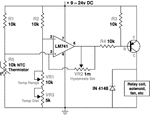
I designed this thermostat by using OP-AMP LM358 and LM35 temperature sensor.but the annoying problem with this circuit is that the relay is constantly interrupted when a temerature reaches to the desired point (37 celcius).how I can modify this circuit so that the relay remains OFF untill the temperature drops 1°C. it meants when tmperature reaches to 37°C, the relay goes to OFF-state;it remains OFF untill temperature goes below 36°C. belw 36°C the relay goes to ON-state.(I'm not willing to use microcontroller). to see the circuit,click on the following link.
**broken link removed**

uc5u_thermo.png
 
Last edited by a moderator:

Add hysteresis as barry suggested. Below example generates 10mV = 1°C hysteresis.

uc5u_thermo1.png
 

Hi,

you just need some positive feedback (hysteresis).
See it as a "2 resistor voltage divider".
R1 from LM35 pin2 to OPAMP pin3
R2 from OPAMP pin1 to OPAMP pin3

Maybe make R1 = 100 R
Then calculate R2 to cause a (relative) voltage equal to 1°C at OPAMP pin3 with taking opamp_output_swing into account.

Klaus

added: I see there are no supply voltage stabilizing capacitors. --> Use a big bulk capacitor and a fast ceramics capacitor (this one close to the OPAMP supply pins)

Thanks Klaus.
can you describe more about the supply voltage stabilizing capacitors (type& capacity)?
 

Hi,

did you use an internet search or a forum search?

--> "power supply bulk capacitor calculation" (electrolytic)
--> "power supply decoupling capacitors" (ceramics, often used: 100nF X7R at each supply pin of each IC)

Klaus
 

bimetallic clock-spring and a mercury bulb switch
worked for many decades. But that's too simple
and reliable.
 

But that's too simple and reliable.

If I am not mistaken, most common water heaters (geysers) still use a bimetallic strip as the temp sensor. My clothes iron also have a bimetallic strip to set the temp.

Bimetallic strip has a built in hysteresis and works very well if you do not care for great accuracy.

Our lab water baths (that was about 50 years ago) had a mercury bulb thermostat; the bulb was big and the accuracy was very good. Of course the heater was run via a relay (but that was long ago).

Of course you cannot maintain a constant temp in a very large bath (even with good stirring) - unless you put the whole bath in a Dewar flask. The best you can do is to have several sensors at strategic places.

I have used a mercury Beckmann thermometer (in my student days) that can read directly upto 0.001C using a simple magnifying glass.

Complex technology has now replaced simple tools!
 

Hi,

did you use an internet search or a forum search?

--> "power supply bulk capacitor calculation" (electrolytic)
--> "power supply decoupling capacitors" (ceramics, often used: 100nF X7R at each supply pin of each IC)

Klaus

good suggestions.thanks.
Klaus, I simulated your idea and inserted positive feedback to the circuit. but finding the true values of R1&R2 are still a bit vague to me.

THANKS FOR YOUR VALUABLE CONCERNS.
 

Hi,

but finding the true values of R1&R2 are still a bit vague to me.
Why vague? It's just mathematics. All input values should be known or (in doubt) measurable.

Klaus
 

finding the true values of R1&R2 are still a bit vague to me.

The feedback resistor is usually a much higher value than the input resistor.
Try substituting a potentiometer for the two resistors.

The values in post #25 have 1M for the feedback resistor and 2k for the input resistor. Thus the input gets a combination of 1/500th of the op amp's output voltage, as compared to what comes through the input resistor. If you find this combination creates too narrow turn-on/off hysteresis range, then adjust them to yield a lower ratio, thus widening the turn-on/off range.

- - - Updated - - -

Since you're working with temperature variations, it takes a lot of cycles, and a lot of time (perhaps days) to achieve the right adjustment.
 

The 1/500 feedback factor would be valid for ideal 5V OP output voltage. LM358 has lower saturated high output voltage, you can correct the feedback according to real output swing e.g. 1/380.

There's a lot of text books, application notes and tutorials teaching OP circuit design, thus I believe you can do some simple calculations on your own.
 

. but finding the true values of R1&R2 are still a bit vague to me....

In my personal opinion, you are starting at the wrong point. First you need to state your requirements.

Just to give an example, you may state that you want a room to be maintained at a const temp. It is wrong to give a fixed temp (say 37C) and you must specify a range (37 +/- 0.1C; something like that)

Then you need to specify the load: is that a room filled with air or a small bucket filled with water? That is important because that will determine the heater size. The heater size must be only slightly larger than the losses (heat lost from the bath).

Then you work on the sensor; are you going to take the temp reading only at one point (ok for small baths) or at multiple points (essential for big rooms). That also determines the final accuracy of temp you are aiming...

Next you work on the fan or the stirrer (essential if you want the temp to be more or less uniform all over the vessel) but they too contribute some heat...

Finally you need to specify the ambient conditions (the inside of my room is 35C and the outside is 42C and I want the room to be 30C only)- this is also very important.

Finally you must tell the actual content: how may people are there in the room (how much heat they are producing) or the water bath (are you using that in the chemistry lab?)- we want to know the amount of heat being produced by the vessel and you should not be adding more heat that it can take...

The electronics part is the least important component. You need to work on a tentative specification to start with.
 

Hi,

In my personal opinion, you are starting at the wrong point. First you need to state your requirements.
(Usually it´s me asking for requirements ;-) )

But here the OP gave a hysteresis of 1°C and LM35, which results in 10mV input hysteresis.
And he showed a schematic with 5V supply and LM358, resulting in an output voltage switng of about 3.8V.
And I recommended that R1 may be chosen to be 100 Ohms.

That´s complete information to calculate R2.

Klaus
 

I see many new questions that have been already answered along this thread. The application has been specified as small egg incubator with moderate accuracy requirements. They assumptions may be wrong or right, but there's no reason to question it for the time being.

The 1 K hysteresis spec has been added later, in the given context I don't think that the absolute hysteresis amount is particularly critical.
 

Status
Not open for further replies.

Similar threads

Part and Inventory Search

Welcome to EDABoard.com

Sponsor

Back
Top