Continue to Site

Welcome to EDAboard.com

Welcome to our site! EDAboard.com is an international Electronics Discussion Forum focused on EDA software, circuits, schematics, books, theory, papers, asic, pld, 8051, DSP, Network, RF, Analog Design, PCB, Service Manuals... and a whole lot more! To participate you need to register. Registration is free. Click here to register now.

[SOLVED] How many LEDS Off a 555

Status
Not open for further replies.
Not sure what you mean by "work out", don't know if you have the datasheet, I imagine you do, or even if it's specifically the SN7474, but this is the TI one:

**broken link removed**

The function table is the least painful way of understanding the device (X means "don't care", i.e. whether a pin has an input that is H or L is not important for the output state), besides the recommended operating conditions.

You have an electronics shop IN your town? - I'm envious.
 

Well i meant figure it out/follow instructions ha.

I havent done much of this, just copied some images, put this here put this there ECT ECT.

Yes thats the datasheet im using :).

Oh we have 2 and one more about 5 miles away, theres nothing here we dont have really part from a Mosque.

- - - Updated - - -

Got it now :)
 

An SN7474 needs a regulated 5V supply, a CD4013 is fine with 9V.
The output of an SN7474 does not go very high and with low current, minimum about 2.4V which is barely high enough to turn on a darlington transistor. The output of a CD4013 goes almost as high as its supply voltage (about 8.5V) with plenty of current to turn on a darlington transistor. Use a CD4013.

EDIT: I see you have a 74LS74, which has even lower output current than an ordinary 7474. Don't use it in your circuit.
 

Oh yeah of course, I always forget to check something :-(.
Thanks
 

Okay a step futher :).

No tansistors

I have my 4013 hooked up and its flashing 2 LEDS off and on (Testing purpose),

The output on Q and NOT Q is : 22.22mA says the DVM without the 2 LEDS and resistor

Doesnt seem right?


With transistors

When i connect the output of the 4013 to the base of the transistor it does not flash the LED it just stays on.
 
Last edited:

Okay a step futher :).

No tansistors

I have my 4013 hooked up and its flashing 2 LEDS off and on (Testing purpose),

The output on Q and NOT Q is : 22.22mA says the DVM without the 2 LEDS and resistor

Doesnt seem right?


With transistors

When i connect the output of the 4013 to the base of the transistor it does not flash the LED it just stays on.

A 555 can be used as a flip flop and it's 15V tolerant.
 

So are you saying i dont need a 4013?
 

Throwing a spanner in the works now ha.

Im running 87 LEDS @ 3.2 fv + 20mA each LED.

Isnt that a monostable, i see a switch
 

The switch toggles the output (On/Off).

What are you looking to achieve? Flash one word and then another? Or flash individual letters?
 

Yes flash EURO then TECK

I dont want to be pressing a switch each time to toggle.
 

If thats it a flip flop isn't needed. You can use the 4017. Wire output 0 to the transistor controlling all leds for EURO, output 1 to the transistor controlling all leds of teck and output 2 to the 4017 reset (to start again)
 

Ive got it working through trans now!.

- - - Updated - - -

Isnt a 4017 a flip flop :-S
 

If you want to be really smart you can even ditch the 4017.
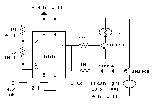
555light.gif


This example setup shows two bulbs being driven by a PNP and NPN transistor each time the 555 toggles its output. With leds you have to watch the polarity and add resistors, but its essentially a case of replacing one of your NPN darlington's with a PNP variant.

Or, since this is low frequency, drive a DPDT relay directly from the 555 output and ditch the transistors too ;)

Edit: A SPDT relay would also work.
 

Thank you for the information and the change of design but i think im going to stick to the previous, design as i have the parts now.
 

Never mind changing the design so it can flash low current light bulbs instead of the high current of all your LEDs.
You measured 22mA at the outputs of the CD4013 by SHORT CIRCUITING IT with a current meter. You are lucky it is not destroyed because its poor little output transistors were heating with 9V x 22mA= 198mW but the maximum allowed heating is 100mW.
 
No its still working so i was lucky.
 

I seem to have a problem with the OUTPUT when the two transistors are linked.

So i have Q going to one transitor and Q NOT going to another transistor.

But the LED stays on OUTPUT Q

and stays off on OUTPUT Q NOT

,If i only have one Q to the transistor it flashes, off and on

when i put the logic probe to the OUTPUTS Q and Q NOT - IT Flashes Hi and Low like it should.

I have D going to Q NOT and the only way i can get the 2 lights to change is by disconnecting and reconnecting Q NOT and the only change once then stop
 
Last edited:

Hi there!

Without seeing your schematic, from what you say it is possible that the transistors need a pull-down resistor from their bases to 0V/GND to keep them turned off when they should be off, and in this way tying them to an appropriate logic level, as they can float a little without one and I imagine the transistors are not identical (might be worth having a look if you have an hFe tester on your multi-meter, just out of curiosity) which is one reason one stays on and the other off.

I have seen this happen with an S/R latch, which is a kind of flip-flop. Yours may be a D-type flip-flop, I don't know without looking, don't think it's a JK.

I think some-one mentioned using a 1K or a 10K resistor tying the bases to ground a few pages ago.
 

Hello Pal

Yeah i was thinking thataat one stage but i havent tried it yet, i will do now.
Its a D-Type DUAL CD4013BE

I know what you men by floating!.
 

Status
Not open for further replies.

Part and Inventory Search

Welcome to EDABoard.com

Sponsor

Back
Top