Continue to Site

Welcome to EDAboard.com

Welcome to our site! EDAboard.com is an international Electronics Discussion Forum focused on EDA software, circuits, schematics, books, theory, papers, asic, pld, 8051, DSP, Network, RF, Analog Design, PCB, Service Manuals... and a whole lot more! To participate you need to register. Registration is free. Click here to register now.

[SOLVED] How many LEDS Off a 555

Status
Not open for further replies.
If you get a batch of LED's and test them with a 9V battery and choose the R for the desired current 1mA ( 6k) or 2 mA (3k), or 10mA (600R) or 20mA (300R) whatever and then sort the Vf in increment bins

My batches come in within +/-0.1V All that matters is the total strings addup to match. The Vf at low currents are all the same for the same colour wavelength . The variation is the ESR which is ~15 Ohms or so.
 
The aim of my project is to make a Word (Englewood or Euroteck) flash across from E - D and repeat it self at a certain speed.

Idealy i would like lets say EURO to flash in WHITE and TECK to flash in BLUE.

WIth a few more parts between 4017 and transistor, there are many variations you can do., with diodes.

Q0 E
Q1 U
Q2 R
Q3 O
Q4 EURO
Q5 T
Q6 E
Q7 C
Q8 H
Q9 TECH
repeat
If you can handle the current.

WHen I did this for a friend in a band back in the 70's, I used Triacs and he used Fat Albert bulbs. Then their "Roadie" changed it to bigger ( but not big enough) Tracs and stage lights. The clock was variable speed from front panel with a slider and he eventually fried the Triacs , sequencing big flood lights at the speed , optimum for maximum repetitive surge currents ~8x average 10A.
 

Im back :), might be bad news for some haha!!.

Oaky so I received 50 blue LEDS today and 50 White, so I tested every one for the fV.

I had 30, 3.05v white
15, 2.95v white the other 5 was above 3.20v+ so im not using them.

I had 33, 3.20v blue
15, 3.18v blue others was to high again

Now im seeing blue and white lights instead of a pc screen :).

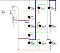
So I decided to think about how I was going to wire each letter, ive started with E now its 9 letters and I need to only wire 2 LEDS in series I presume.

Ive attached a rough copy of the letter wired.
Now the Blue wires are coming from 9 volts
The Green wires are the connecting wires connecting 2 LEDS
The RED wires is coming from the Collector.

All LEDS ARE 3.2 fV and 10mA

But only the D12 LED lights UP. Its a single LED on its own as its an odd letter.

What have I done wrong now :-( ha.


- - - Updated - - -

WIth a few more parts between 4017 and transistor, there are many variations you can do., with diodes.

Q0 E
Q1 U
Q2 R
Q3 O
Q4 EURO
Q5 T
Q6 E
Q7 C
Q8 H
Q9 TECH
repeat
If you can handle the current.

WHen I did this for a friend in a band back in the 70's, I used Triacs and he used Fat Albert bulbs. Then their "Roadie" changed it to bigger ( but not big enough) Tracs and stage lights. The clock was variable speed from front panel with a slider and he eventually fried the Triacs , sequencing big flood lights at the speed , optimum for maximum repetitive surge currents ~8x average 10A.

Im still getting use to wiring LEDS up, now your getting technical :). but sounds a good idea
 

add a series R to the single LED such as 5.5V/10mA= 560 Ohm.

But I suspect the 2N2222 will load down the 4017 output with a 300 Ohm source impedance @ 9V and the transistor input impedance from (10 to 20)*Re + 50 probably drops Vb in half.

try again.

- - - Updated - - -

I think you need a full design to follow and no one knows what power supplies you have avail.
 

Why don't you understand that two 3.2V LEDs in series need 6.4V but the single LED needs only 3.2V so the pairs of LEDs are not getting their required 6.4V?
Like I explained before about having LEDs in parallel then the one with the lowest voltage (your single LED) hogs ALL the current and soon burns out.

When the single LED has a series resistor that has a 3.2V voltage drop then the current limited by the 10 ohm resistor is about 210mA. Then each LED conducts 35mA. Why did you think they conduct only 10mA? Most ordinary 5mm diameter LEDs burn out with 40mA of continuous current.

Is the 9V a regulated voltage?
 

Hey guys,

I'm still learning that's why I make mistakes.

I just wanted to show how I would wire up a Letter with LEDS, now I know I need a resistor to run the one LED.

I do understand that 2 x LEDS in series needs 6.4V and now I know I need a resistor for the one LED.

9 - 3.2 x 0.001 = 580

Its a 9V supply not regulated on the Sche.


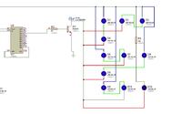
Ive added another string to my design.

All LEDS are 3.2V 10mA
But the LEDS don't light up on the letter U but does on the letter E , the collector current is 1.3 on the U but 6.1 on the E
Ive made a PDF sche (Check Me Out :))


It says 18V on the PDF ignore that cause its 9V supply.

I know im a pain in the ass but im here to learn
 

Attachments

  • Euroteck LIghts.PDF
    54.4 KB · Views: 152
Last edited:

Hi there!

Don't be daft, you're not being a pain, lively debate and helping is why people come here I imagine.

I'm going on a post from this morning/last night: Considering all LEDs at 3.2V, and looking at the schematic with 11 LEDs

Assuming an optimistic, but not necessarily fully available 9V

Forward voltage x 2 LEDs = 6.4V

9V - 6.4V = 2.6V
2.6V/0.020A = 130 Ohms

9V - 3.2V = 5.8V
5.8V/0.010A = 580 Ohms

Sorry to be boring and obvious... Resistors in series are added R1 + R2 + R2, resistors in parallel are divided by the number of parallel resistors, 1/Rtotal = 1/R1 + 1/R2 + 1/R2. In series and parallel circuits each parallel string is added as though it were series, then those results are treated as parallel resistors.

Resistors in parallel, for arguments sake putting one resistor on each string:

5 parallel resistors for 5x2 parallel rows, 1 resistor for 1x1 parallel row (6 parallel rows):
a) 1/130 = 0.008 x5 = 0.04
b) 1/580 = 0.002
a + b = 0.04

1/0.04 = 25 Ohms


Or, as you have/had:

1 series resistor for 5x2 parallel rows, 1 resistor for 1x1 parallel row (6 parallel rows):
1/130 = 0.008 + 1/580 = 0.002 = 0.08
1/0.08 = 13 Ohms

Bla, bla, bla...

If possible try to have an even number of LEDs in each letter, and the resistor calculations will be a lot easier/will only need one series resistor from V+ for each set of parallel LEDs in each letter.
At 12V I had parallel strings of 3 x 3 LEDs, and 1 x 2 LEDs, the two LEDs had a larger value resistor to compensate for the "missing" LED. I used one resistor for each 3 LED string, and it took ages to get the value of each right using an ammeter.

If you have one and you're comfortable with a DMM on the ammeter setting, you could see how much current is going into each parallel string from V+, and that way calculate the resistor according to each reading - slow but sure results.

If your supply has a 12V setting, I'd use that, should be able to put 3 LEDs in each parallel string, if not 9V is okay for 2 LEDs.

Probably has nothing to do with anything in this thread, small point, took me ages to realise why everything gets de-rated (at first I thought what's the point of 1 Amp output/12V rated capacitors if in practice only half rated use is often advisable): not good to drive a car at full revs and pedal to the floor, won't last long not built for that, same with everything.

" The clock was variable speed from front panel with a slider and he eventually fried the Triacs"
Reminds me of a parody of a car advert years ago. Original read something like: "Designed by engineers, cut by lasers, built by robots.", parody read something like: "Designed by engineers, built by robots, and crashed by idiots.", for some reason it always comes to mind when I'm bread-boarding, don't know why...
 

Why don't you understand that two 3.2V LEDs in series need 6.4V but the single LED needs only 3.2V so the pairs of LEDs are not getting their required 6.4V?
Like I explained before about having LEDs in parallel then the one with the lowest voltage (your single LED) hogs ALL the current and soon burns out.

When the single LED has a series resistor that has a 3.2V voltage drop then the current limited by the 10 ohm resistor is about 210mA. Then each LED conducts 35mA. Why did you think they conduct only 10mA? Most ordinary 5mm diameter LEDs burn out with 40mA of continuous current.

Is the 9V a regulated voltage?

Well didn't someone say that the output of the transistor is 100ma?
So I have 11 LEDS in E.

So do I divide 100mA by 11 and then set the ma for each led?

Theres lots of different replies
 

Hey Englewood, nice pdf schematic. I'm missing something important or getting very absent-minded as there is no resistor on the 5 x 2 LEDs, going on my super maths above they also need (to share) a resistor to limit the current, and if I didn't get something wrong it would be about 130 Ohms.

I implore you :) - put the power-up reset capacitor and resistor in the schematic I did on the reset pin, unless you want it to randomly start on "N", or "W", or "O", instead of "E", because it will.

The non-output of the "U" is a mystery to me, sorry, it should work if it is physically wired the same as "E" and "E" works. Check for breadboard gremlins - they are very sly and can play tricks on your eyes, cables in the adjacent hole or wrong place but look right at first glance.

- - - Updated - - -

Whatever, the transistor is like a tap which puts out however much water is demanded of it (up to its limits), the LEDs are greedy, they need to be controlled by the resistors. Takes a while to realise there's a fine line between supply and heading for a short circuit there...

The LEDs with the right resistors will demand 110mA, the transistor can provide (if it's a 2N2222A) about 300mA for short periods of time, continuous is "not recommended" as the datasheets for other things say, I don't know the BC517.

- - - Updated - - -

Just remembered. The letter "U". All LEDs I had used were long anode lead and short cathode lead, until one day I got a batch with long cathode lead and short anode (a bit confusing as to why they didn't turn on), that might be a reason too, but unlikely. A 3V flat round battery (can't remember name, like an old motherboard clock battery) is usually enough to test them and fits nicely between the pins.
 

Well didn't someone say that the output of the transistor is 100ma?
So I have 11 LEDS in E.

So do I divide 100mA by 11 and then set the ma for each led?
Nope. Before, the 10 ohms resistor limited the current to about (9V - 6.4V - 1V)/10 ohms= 160mA where the 1V is the on-voltage of the darlington transistor. Now you do not have the current-limiting resistor so the current is UNLIMITED! It could be 10A or 100A just before the LEDs and transistor blow up.

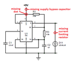
By the way, your schematic shows a transistor but you do not have a transistor. Instead you have a BC517 darlington and I think most of us have never seen one so we assume it is an ordinary little transistor like you show on your schematic. Please use the symbol of a darlington.

Why do you use the extremely low value for the 50 ohm base resistor that is shorting the outputs of the CD4017? I calculate a value of 71,000 ohms (use 68K).
Why do you have an LED (D11) that is shorting the output of the 555 and is being destroyed by its unlimited current? An LED should ALWAYS have something (a resistor?) in series to limit its current.

I corrected errors on the 555 part of your schematic and eliminated all the ups, downs and arounds that Multisim does with wires.
 

Attachments

  • 555 oscillator.png
    555 oscillator.png
    11 KB · Views: 118
  • Like
Reactions: d123

    d123

    Points: 2
    Helpful Answer Positive Rating
I'm willing to use any supply but if its going to alter things then I might as well just stay with 9v.

I know about resistors in para and resistors in series and the calculations but I've never put them into practice until now.

Maybe this circuit was too advanced for a starter circuit but it will give me knowledge in building a circuit.

I was testing the LEDS for current and it was up and down but i don't think i had them setup on the breadboard right, i dont think the resistor was doing anything.

I understand this

Forward voltage x 2 LEDs = 6.4V

9V - 6.4V = 2.6V
2.6V/0.020A = 130 Ohms

9V - 3.2V = 5.8V
5.8V/0.010A = 580 Ohms

It was not on my Sche because I was just testing at the time.

I need to learn more of the maths, you seem much more advanced than me by the looks of things.

- - - Updated - - -

Thank you Audioguru.

I don't even know what the symbol for a Darlington is, I assumed its just a NPN transistor :-0. Yes its defiantly different (Google)

I copied it from a previous reply.

I had the LED to see how fast the 555 timer was acting, again I just put it there with out thinking.

A LED MUST ALWAYS HAVE A CURRENT LIMITING RES (Ive got this now)

So ive made the changes and the 4017 is outputting correctly but my one single LED is brighter than the rest and the others are very dull.

- - - Updated - - -

Does it need a bypass cap its just DC?
 

Your maths do not include the voltage across the darlington (shown on its datasheet) when it is turned on.

Since your single LED is brighter than the rest of the LEDs then its current must be higher. Increase the value of its current-limiting resistor until its brightness is the same.

The datasheet for the LM555 recommends TWO supply bypass capacitors. One reason is that the 555 draws 400mA from the supply the moment its output switches that disturbs its timing and disturbs other logic like the CD4017. The bypass capacitors hold the supply voltage up during the 400mA spikes. ALL ICs need a supply bypass capacitor with very short wires very close to the ICs.

Does your 9V power supply have voltage regulation? I hope it is not a little 9V battery that drops its voltage when you try to draw current from it. I also hope it is not a cheapo ebay wall wart adapter that is maybe 15V or more when it has low load current.
 

Yes I did that got to the same sort of brightness, I guess it doesn't have to be very accurate as its just a light and you cant see much of a difference.

Ah I see so I need to work out a value capacitor for bypass cap too Arghh! ha.

No its not a 9V battery it does have voltage regulation, its always a steady 9.06V constant no changes.

D123

I can see what you mean by keeping the letters even LEDS but that one extra LED can make a letter look messed up for sure.

You guys are clever do you have a TV :),
 
Last edited:

I need to work out a value capacitor for bypass cap too Arghh! ha.
No, you do not work out anything, you simply read the datasheet for the 555 and for every other IC and transistor you use.
The minimum bypass is a 0.1uf ceramic capacitor for high frequencies that I always use and a 1uF electrolytic for low frequencies but I would use 10uF.
 

Attachments

  • LM555 bypass caps.png
    LM555 bypass caps.png
    12.7 KB · Views: 119
Hey Englewood!

With my unhealthy and biased zeal for PET capacitors, I'd recommend 0.1uF (100nF) ceramic (MLCC) or PET, and 1uF PET in parallel for the 4017, and - make a manufacturer and a retailer happy! - a 0.1uF ceramic, a 1uF PET and a 10uF PET in parallel on the supply pins of the 555.
PET is great, good for predictable timing (and a lot of other things at low uF values), electrolytic isn't, but it is good for power supply filters, pardon me.
You're funny, to be clever would be nice, but I'll settle for not too bright (get it - also refers to LEDs!, not yours, just a bad joke). Hang on, I don't have a TV, thank goodness, waste of time and neurons.

Sadly, datasheets are those annoying things that a quick scan of the pinout followed by the typical applications section, oh and the absolute maximum ratings and those funny looking graphs, become absorbing reading after a while, I still don't understand them but they are very informative!


Hope it's going well.
 

Hey pal, hmm my brain is dying slowly haha.

PET, I have a Malamu Husky.

I DONT BLOODY BELIEVE IT!!!

I had 4 letters all working good then I thought I saved my work and my laptop dies and lost it great :-(.

Now I've re-done a letter and the LEDS don't light up.

3.2fV/10mA all LEDS - PDF attached **broken link removed**

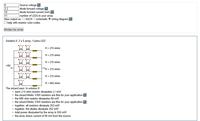
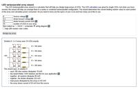
Also I was looking at LED/SERIES in Para on the net.

Found this why are the values different, from the ones you have calculated?


Your new PDF attachment does not open.
The "wizard" does not have the 1V voltage drop of the darlington transistor and the single LED has a current of only 8.5mA instead of 10mA.
Notice that each string has its own current-limiting resistor like we originally wanted but you wanted only one current-limiting resistor for many strings.
 

View attachment Euroteck LIghts.PDF

Ah that makes sense!.

- - - Updated - - -

Okay then so I have 8V and not 9V.

I have 10 LEDS/10mA in Para and I want one Res.

If I was going to use the WIZARD

I would just ADD the 5 RES together to make one, which will make 900 or just use a 180 not 130 :-S

Im just trying to get a better understaing

 
Last edited:

Status
Not open for further replies.

Part and Inventory Search

Welcome to EDABoard.com

Sponsor

Back
Top