Continue to Site

Welcome to EDAboard.com

Welcome to our site! EDAboard.com is an international Electronics Discussion Forum focused on EDA software, circuits, schematics, books, theory, papers, asic, pld, 8051, DSP, Network, RF, Analog Design, PCB, Service Manuals... and a whole lot more! To participate you need to register. Registration is free. Click here to register now.

High side IGBT damaging

Status
Not open for further replies.
Sounds like there is a fair bit of leakage inductance in your transformer to generate these spikes (and/or slow o/p diodes) can either increase the turn on Res to the igbt's, slowing down the turn on, and/or, bigger snubbers on the diodes (double the C and tune the R for best performance - lowest spike voltage) they will dissipate more heat tho..!
 
Sounds like there is a fair bit of leakage inductance in your transformer to generate these spikes (and/or slow o/p diodes) can either increase the turn on Res to the igbt's, slowing down the turn on, and/or, bigger snubbers on the diodes (double the C and tune the R for best performance - lowest spike voltage) they will dissipate more heat tho..!
Hello guys with the welder transformer everything is working fine and now i want to wind my own transformer.. I started with this document "slup229" but i have an problem that i'm not understanding the part where they calcolate the primary turns can anybobdy help me ? It's on 3-8 pdf's page
 

The V/T (Volts per Turn) ratios on the secondary are determined by the minimum primary voltage and maximum duty cycle to regulate the secondary.
The V/T ratio on the primary is determined by input line peak voltage range and the allowed voltage on the output rectifiers.
The primary:secondary turns ratio determines the maximum voltage ratio.

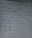
hello guys i did these calculations will you please check these?

- - - Updated - - -

20150728_202019-1.jpg

sorry
 

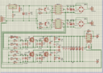
hello guys like you all said i changed my gate driver and this my new circuit:
Catturam,m.PNG

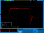
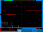
but gate waveform is still not ok i don't know what is causing this... please help
òlll.pngmnm,m,n,mnm,.png

- - - Updated - - -

The V/T (Volts per Turn) ratios on the secondary are determined by the minimum primary voltage and maximum duty cycle to regulate the secondary.
The V/T ratio on the primary is determined by input line peak voltage range and the allowed voltage on the output rectifiers.
The primary:secondary turns ratio determines the maximum voltage ratio.

please help....
 

Hello guys with the welder transformer everything is working fine and now i want to wind my own transformer.. I started with this document "slup229" but i have an problem that i'm not understanding the part where they calcolate the primary turns can anybobdy help me ? It's on 3-8 pdf's page
The flux swing in the core is determined by the volt microseconds on the primary. The higher the voltage, or the longer the primary voltage is applied, the more turns that will be required for any given flux density.

The hardest operating condition the core sees, will be at maximum full duty cycle, which should only occur at minimum supply voltage and absolute maximum load.

At less than full load, or at higher input voltages the duty cycle will be much reduced, so its less stressful.

So what you design the primary turns for is lowest input voltage, and maximum full duty cycle at the switching frequency of your choice.

Np = (primary voltage x microseconds turn on) divided by (flux swing in Teslas x core cross section in mm squared).

Its pretty straightforward apart from choosing a suitable flux swing.
Above about 30 Khz core losses start to climb, and acceptable temperature rise of the core is what you need to think about.

Basically, if its burning up under no load, you need to reduce the flux swing by adding more turns.
 

try taking the 1nF caps off the gates..! also twisted pair wire from the driver to the igbt's...! it appears the 3120's have good enough pull down capability so the wiring in between must be the culprit, avoid any obvious loops...!
 
try taking the 1nF caps off the gates..! also twisted pair wire from the driver to the igbt's...! it appears the 3120's have good enough pull down capability so the wiring in between must be the culprit, avoid any obvious loops...!

Hello orson last night i found that the spikes on turn off are related to the spikes on drain to source picture, i tried to change the snubber resistere to supress that spike and i noticed that when the spike on the output waveform it also reduces oscillations on gare drive waveform... But i can't can't supress that spike i tried many values of capacitore and resistore but spike remains...
Pls help... Thanks..
 

You need a tighter layout with the igbt's close together, and film caps close across the +HVDC and power diodes (D17, D18) that turn on a bit faster, also close by, this will reduce the overshoot and help with the common mode effect that is getting thru to your gate drive...but twisted pair wires to the gates and removing the 1nF should help...!

- - - Updated - - -

you haven't posted any pics of your layout have you?

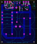
this is the board that i'm using for now....
dd.PNG
 

the diodes in the igbt snubbers are a bad idea... unfortunately single sided pcb layout leads to wiring inductance leads to turn off spikes....
 

Status
Not open for further replies.

Part and Inventory Search

Welcome to EDABoard.com

Sponsor

Back
Top