Continue to Site

Welcome to EDAboard.com

Welcome to our site! EDAboard.com is an international Electronics Discussion Forum focused on EDA software, circuits, schematics, books, theory, papers, asic, pld, 8051, DSP, Network, RF, Analog Design, PCB, Service Manuals... and a whole lot more! To participate you need to register. Registration is free. Click here to register now.

High side IGBT damaging

Status
Not open for further replies.
Static IGBT losses for new part can be modelled as Vce*Ice=P=(1.25V +0.01Ω*Ice)*Ice.

Thermal Resistance is unknown for your heatsink and interface, while Rjc is only 0.27'C/W Do you have a CPU heat sink?

Is this a bipolar output with centre ground load?
That would explain the asymmetric pulse widths to mid-level Voltage.

Drivers need to be able to transfer Gate charge ~1mJ or current limit of Ig x transition time. The test parameters used Rg=3, so driver ESR must be examined and // IGBT's factored.

ESR is usually 10x Rb for a saturated driver switch. where Rb is 330R?
Better ones are up to 50xRb, based on Vce(sat) Ic/Ib rating.

my rule of thumb is to compare impedance gain of each stage.

this is my refrence circuit:
reg60v.png

this is a full project website:
http://danyk.cz/reg60v_en.html
 

i don't have instruments to measure switching and conductions losses in the igbts,
Most people can't measure the losses directly, especially switching losses, I'm asking if you tried to predict them based on the device datasheets. You can get good approximations with the right methodology. That method can be adapted to IGBTs and other topologies.
but i tried to calculate the efficinecy with measuring dc bus voltage and currente and output voltage and current and it's about 70% like expected from a forward converter.
IMO 70% is quite low, especially at such a high power level. I would expect closer to 85% at full load, with only up to half the losses being in the IGBTs.


Ditch the output transformer, and go back to running just a resistive load.
Run it at 50 Khz, then run it again at 1khz or 5Khz at the same duty cycle.

If it still burns up it can only be either high conduction losses, or insufficient heat sinking.

If it runs fine at low frequency, it can only be a switching loss problem.
 
  • Like
Reactions: yogece

    yogece

    Points: 2
    Helpful Answer Positive Rating
You have to make sure the fets are off long enough for the Tx to reset, if not the flux will walk up to saturation quickly and large currents will flow in the igbt's giving very rapid Vrise at turn off (which we are seeing) and loads of heat, also you see the source current go up, You appear to have a control problem.... more off time required, limit the on time to <50%, say 40% for starters max...!
 
hello guys thanks for helping me today i decided to monitor the gate waveforms.

when i was going up with voltage at about 48 volt and 6.5 ohm resistive load i started seeing this and input current rises:

oggi.png

- - - Updated - - -

i tried also with 800 watt lamp no problem with heat it (trasnformer disconnected)

- - - Updated - - -

i noticed one another thing when everything is cool that pulse in in gate waveforms don't appears it starts appearing when mosfets are about 50C of body temprature
 

Do you have any specifications on the transformer?
Number of primary turns, type of core ?

Also anything you can tell us about the rectifiers and choke.
 

Do you have any specifications on the transformer?
Number of primary turns, type of core ?

Also anything you can tell us about the rectifiers and choke.

i'm using transformer of an welding machine: svm183
also the rectifier diodes are from welding machine

- - - Updated - - -

output choke is an 30uH
 

I did find a service and repair manual for the svm183, but it had nothing of real help or relevance, except it runs at 80Khz (not 50Khz).
That might become a problem for the transformer at max input voltage and full duty cycle if run at 50Khz.

One other thought.
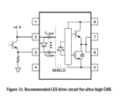
The HCPL3120 opto can be prone to common mode noise problems when used as a high side driver, unless the led side is designed carefully.
I have had problems with this in the past myself...
Scroll down to page 21 in the application notes:

This common mode noise problem might account for some of your troubles.
Its just one more small detail to take notice of.
Physical layout can become critical too, at high switching speeds and high power.
 
  • Like
Reactions: yogece

    yogece

    Points: 2
    Helpful Answer Positive Rating
yes, your gate drive needs fixing, that extra bit of fuzz after turn off will cause the heating you are seeing...
 
I did find a service and repair manual for the svm183, but it had nothing of real help or relevance, except it runs at 80Khz (not 50Khz).
That might become a problem for the transformer at max input voltage and full duty cycle if run at 50Khz.

One other thought.
The HCPL3120 opto can be prone to common mode noise problems when used as a high side driver, unless the led side is designed carefully.
I have had problems with this in the past myself...
Scroll down to page 21 in the application notes:

This common mode noise problem might account for some of your troubles.
Its just one more small detail to take notice of.
Physical layout can become critical too, at high switching speeds and high power.

so i have to add this transistor and try again?
Cattura11.PNG
 

There is still no adequate reset time on the oscillographs, try running at lower duty cycles on the gate, you will then see reset of the Tx (on the drain of the lower device - should be some ringing after a reset of the Tx), when you increase the Ton such that there is no proper reset, the currents will go up and the fets/igbt's will get hot...!
 
There is still no adequate reset time on the oscillographs, try running at lower duty cycles on the gate, you will then see reset of the Tx (on the drain of the lower device - should be some ringing after a reset of the Tx), when you increase the Ton such that there is no proper reset, the currents will go up and the fets/igbt's will get hot...!
So what i have to do for resetting the TX core ? Change the diodes?
 

put in a pot so you can manually turn down the duty cycle, use this to see the max ON time you can get before you run out of reset on the Tx....
 
put in a pot so you can manually turn down the duty cycle, use this to see the max ON time you can get before you run out of reset on the Tx....

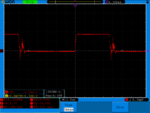
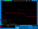
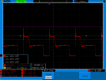
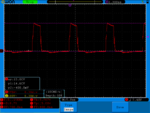
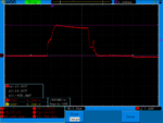
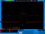
hello guys i'm getting these waveforms on gate and drain to source of low side igbt:
1.png2.png3.png4.png

- - - Updated - - -

these spikes increases with load i these breaks the igbts how can i limit them?
 

your gate turn off is not good enough... have you posted the circuit for the gate drive?

- - - Updated - - -

The high voltage spikes at turn off indicate you don't have film caps across the rails close to the fets...
 
your gate turn off is not good enough... have you posted the circuit for the gate drive?

- - - Updated - - -

The high voltage spikes at turn off indicate you don't have film caps across the rails close to the fets...


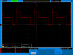
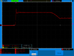
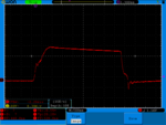
hello sir thanks a lot for helping with capacitors on the igbts it changed a lot and now also the temprature of heat sink is much stable (36C) and the room tempraure was (30C)
thease are the waveforms now.
11.png22.png33.png44.png

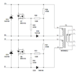
because i burnt one of my hcpl-3120 now for gate drive i'm using this circuit:
kjj.PNG
i have to wait until i get another hcpl-3120

if the wavforms are ok it's safe to try putting some another load ?

for now i'm running at 24Volt and 28Amp on resistive load...
dc bus voltage is 300volt and the current is 2.9Amps
 

Status
Not open for further replies.

Part and Inventory Search

Welcome to EDABoard.com

Sponsor

Back
Top