Continue to Site

Welcome to EDAboard.com

Welcome to our site! EDAboard.com is an international Electronics Discussion Forum focused on EDA software, circuits, schematics, books, theory, papers, asic, pld, 8051, DSP, Network, RF, Analog Design, PCB, Service Manuals... and a whole lot more! To participate you need to register. Registration is free. Click here to register now.

Help! Can someone clarify to me how this converter circuit works?

Status
Not open for further replies.
Ermm...Jz new year..lol

What is the I1? Since I will connect a chopper at the output, I just connect across RLOAD. Will there be any problem?
 
Oh.... right.

Uhm wrong moon maybe. I was thinking about the Korean New Year because I have been told about that one and, guessed, it might be similar to yours. It turns out I may have picked the wrong new moon,

Korean New Year - Wikipedia, the free encyclopedia

So I should have picked the second one after the winter solstice. 2011 Feb 3rd.

Hope you and all enjoyed yourselves. :)

I1 is just in there for transient testing. You will see I set RLOAD to 100K to 'remove' it from the circuit. I1 was set to 500mA-1.5A 1mS on 2mS period.

Yes you can ignore it and connect your buck at the output, remove RLOAD too but I am sure you knew that.

I should give an update and include the/an optocoupler and also show how you might control both output voltage and current and how to get auxilliary power for the primary and secondary control circuits.

As I suggest you may not need the buck converter in order to control charging of your battery.

Genome.
 
yaya...2011 feb 3rd=)

Yaya...I know must remove that too.

Sorry, Genome. The title that I proposed is about buck boost converter. Therefore, I should have that circuit. Thank you very much.

---------- Post added at 11:25 ---------- Previous post was at 10:11 ----------

For the transformer winding, which transformer are you suggesting? Can you suggest any from RS?
**broken link removed**

From the website shown, if I use ETD39, the AL value is 2700nH. I think so because there only put 2700.
Since, L=Al.N^2
If L=6.5mH, therefore, N= 49 turns. Will the size of copper affected?
My orders for transformer got some problem. So, at least I think I must have some back up plans.
 
Last edited:

I shall put together a quick transformer design tutorial.

Words sometime later today.

Genome.
 
Thank you. :)
I need to get the copper before going back to my uni as there hardly to go out due to transportation.
 

Transformer Design

Let's start out with some sums. Basic definitions of Inductance and B field.

L = Uo.Ue.N^2Ae/Le

B = Uo.Ue.N.I/Le

Uo is the permeability of free space 4.pi.10E-7
Ue is the effective permeability of the core
N is the number of turns
Ae is the effective area of the core
Le is the effective length of the core

Most of these won't matter its just rearranging the equations to get something useful for our needs. I'm going to be 'evil' and crush them together. If you compare the two then you will see that if you multiply the one for B by Ae.N/I it becomes the one for L... so

B.Ae.N/I = L

We are interested in the number of turns so rearrange that to get,

N = L.I/B.Ae

This is one of the 'good' sums for inductors. In a switch mode power supply inductor you would design for a 'peak' current, average plus half ripple, in the winding and a peak flux excursion in the core. It gives you the minimum number of turns required to satisfy the design requirements in particular peak flux in order to avoid saturation,

Nmin = L.Ipk/Bpk.Ae

Not a 'transformer equation' yet but as suggested the primary, or any winding, on a transformer is itself an inductor.

Mr Faraday said,

E = -LdI/dT

The voltage across an inductor is proportional to the rate of change of current in its winding. Not much use as it stands to us but perhaps Mr Faraday did not know about Switch Mode Power Supplies. So, move things about and,

EdT = LdI

I've been 'evil' again and thrown away the minus sign. You might realise that my maths is not 'all that'. We are lucky to be dealing with 'square' waves so the voltage E over the sort of time period we are interested in is a 'constant'. Call that VIN, in our case the peak(ish) rectified mains voltage.

VIN.dT = L.dI

Now we assume that current in the inductor, our primary magnetising inductance, starts at zero and we apply VIN for the on time of the primary side switches. Since I, not me.. the current, started at zero then at the end of the on time the current in the primary will have changed by by dI and its value, I, will be dI.

VIN.Ton = L.I

That's useful for checking out things like ripple currents in filter inductors. Still not much use for our transformer but if we go back to,

Nmin = L.Ipk/Bpk.Ae

and re-write that as,

Ipk = Nmin.Bpk.Ae/L

then substitute we get

VIN.Ton = L.Nmin.Bpk.Ae/L

L cancels and we rearrange to make Nmin the subject with the result,

Nmin = VIN.Ton/Bpk.Ae

Which gives you the minimum number of primary turns required on the primary in order to avoid exceeding a Bpk value, and saturating the core, based on the other parameters.

VIN.Ton is what is known as a 'volt-second' product. We are lucky because we are dealing with square waves. If VIN was a more complex waveform then we would have to do some of that head hurting integration stuff to determine what the associated volt-second product would be.

My previous use of the Al value was just to get an 'approximate' number to put in Spice. It may still and will be useful at a later date. Unfortunately you may have been mislead slightly into thinking that it is one of the things you 'target' in order to do a design. It is a secondary concern. What we want, and what we now have, is a sum that gives us the minimum number of primary turns required to avoid core saturation.

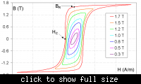
Having said that... Bpk, or more strictly Bsat, may not be the 'real' limiting factor. Here are some B-H loops from Wikipedia,


It is not a material you will be using but it demonstrates the 'issue'. The stored energy is, best I remember, E = 0.5 B x H. As you traverse those BH loops you will see that your route in one direction is different to the one you take on the way back. The area in the middle represents hysteresic power loss in the core which makes it get hot...

It's not a strict relationship but if you double the operating frequency whilst operating at the same designed peak flux excursion you will double the power losses. At some stage you will have to reduce your peak flux excursion to avoid things melting. It's one of the trade off's in the design process. You may see that different core materials are offered. In the case of Siemens/Epcos for example, N27, N67, N87, N97. Each grade offers lower losses at higher frequencies than the one below it.

Power losses are key to the process and get divided into core and copper losses. A general starting point is to work from the basis that they will be equal and therefore assign half of what is 'available' to each. Now you need to know what is available.. The information is out there,

**broken link removed**

https://www.epcos.com/web/generator...operty=Data__en.pdf;/PDF_ApplicationNotes.pdf

On Page 29) you will find Table 6.6) which gives you..

6.6 Thermal resistance for the main power transformer core shapes

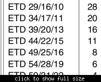
The figures assume a fully wound core and, since I believe in ETD shapes for this sort of application then the ones you need are,


Now we are going to start setting up 'tables'. I realise there are equations that should get you an answer 'faster' but I have never had much luck with them and this method works for me. This is down in the realms of if you wish to find an 'answer' you will have to iterate in order to get there.

I'm going to go away and think about a 'spreadsheet' and the possibility of grubbing up some freebies.

Later

Genome.
 
Hum.. There was a time where this was all available in one download. Now it has, for some reason, been broken up..

https://www.epcos.com/inf/80/db/fer_07/etd_29_16_10.pdf
**broken link removed**

That's OK. I'll just download multiple files and open them in order to find what I was looking for. Grumble Grumble. In this case Ae values.

© EPCOS AG 2006. Reproduction, publication and dissemination of this data sheet, enclosures hereto and the information contained therein without EPCOS’ prior express consent is prohibited.

With apologies to those concerned.

Effective areas Ae, as 'Robbed'.

ETD29 76mm^2
ETD34 97mm^2
ETD39 125mm^2
ETD44 173mm^2
ETD49 211mm^2
ETD54 280mm^2
ETD59 368mm^2

Maybe I should 'dial' the TDK guy and listen to his lack of interest unless I am going to buy a billion.

Ho Hum. I might be burning my boats here.


Next you, I, have to find and look at something like the 'relative core loss per unit mumble curves' for the materials available.

They might be available from here..

**broken link removed**

I know... I'll download the lot as a ZIP file and then try and find it. Pfft. That will be my regular bad hair day..

This is too much like hard work.. Hopefully looking elsewhere... Ahaa..!

**broken link removed**

Perhaps N67 was a figment of my imagination but I am sure it existed in a previous life. That leaves me with N27 and N87.

https://www.epcos.com/web/generator...F/PDF__N27,property=Data__en.pdf;/PDF_N27.pdf

https://www.epcos.com/web/generator...F/PDF__N87,property=Data__en.pdf;/PDF_N87.pdf

Dare I suggest similar data may be available from other manufacturers.

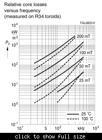
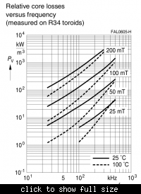
Picking N87 then on Page 5) you get this Graph..


Now I have to go back and look through those, separate, PDF files for Effective Volumes. Grrrrrrrrr!!

Now my SproodSheet becomes..


I might be 'losing it' here so I'm going to stop for the moment.

Genome.
 
Wow. It has been a hard work for you. I'm so sorry for that.

---------- Post added at 05:08 ---------- Previous post was at 04:48 ----------

So, which ETD I should choose? I see from the SproodSheet, the higher the ETD the higher power loss.

By the way, if the converter is operating at 100kHz, the chopper must operate at the same frequency or can operate at different frequency? So, far I'm operating them at the same frequency.

---------- Post added at 06:28 ---------- Previous post was at 05:08 ----------

Sorry, I just realise that the regulator circuit has CT and RT. What are they?

From the earlier post, you were mentioning about R7,R8 to have current 1.5A. If by using the IC, how the connection shown in the diagram helps to regulate the output? The regulator is to regulate both current and voltage?Sorry for jumping here and there.
 
Last edited:

My apologies.. I can be slightly unreliable.

Ideally you would want to synchronise the two circuits so they operate at the same frequency. It helps to stop them interfering with each other.

CT and RT are the timing components.

https://focus.ti.com/lit/ds/symlink/uc3842.pdf

Page 6)


There are equations in one of the other documents but in this case it is simple enough to use the graph from which it looks like setting CT to 1nF and RT to 22K will get you the switching frequency of about 100KHz.

The larger the core the lower its thermal impedance and therefore the greater the power it can dissipate for the same temperature rise above ambient....

I'l continue in a bit but for the moment I now have this on my 'spreadsheet',


From left to right,

The core type. Its effective area, Ae. The thermal resistance, Rth. This is in degrees centigrade per watt. Next is the amount of power it can dissipate if I wish to limit its temperature rise to 40C above ambient. The larger cores with their lower thermal resistance can dissipate more power for the same temperature rise. I split that available dissipation equally between the Core and the Windings, PCU/PCR. Next is the effective volume of the core Ve. Dividing PCR by Ve gives me Pv which is the specific power loss per unit volume that will result in that particular loss for each core.

The N87 relative core loss graph has that value, Pv, plotted on its Y axis.


The X axis is the switching frequency and a family of curves for various peak flux densities is given. As an example if I were to take the ETD29 the Pv Value is 134kW/M^3 which, and it involves a bit of guessed interpolation, would mean I have to limit the peak flux to 150mT. Just to confuse things that peak figure gets doubled to become 300mT.

Whilst the converter is operating in one quadrant of the B-H curve it is still allowed a peak-peak flux excursion as long as it does not exceed the saturation flux density for the material. Filling in the other numbers...


You will notice that you can operate the smaller cores at higher fluxes. You may remember from biology that the surface area to volume ratio determines how well something can get rid of its internally generated heat. The same applies here.

Some time in the past I selected a minimum input voltage of 250V to account for a single cycle line drop out. That will be our VIN. At this point the converter will be operating at the maximum duty cycle of 50% which will give Ton at 100KHz as being 5uS. So, now we can fill in the minimum required primary turns.


I am sorry this is taking some time and possibly time you do not have. Hopefully it, the transformer design, will be finished today.

Back in a bit.

Genome.

---------- Post added at 11:36 ---------- Previous post was at 11:25 ----------

Oh, R7 and R8.

Those are the components on the current sense pin. One is connected to the current sense resistor the other will be connected to the Ramp, RT/CT, pin to provide slope compensation. It is supposedly not necessary for this particular type of converter but does help to define the gain. The ILIM pin has a 1V threshold on it which with a 1R current sense resistor would give a 1A peak current limit. Slope compensation modifies that figure because it introduces a divider and it also injects the Ramp signal. As a result the peak current limit level is modified in this case going from 1A up to about 1.5A.

As mentioned this is 'current mode control'. The circuit controls the inductor current, turning it into a current source... That simplifies the output filter characteristic. As an LC section, ignoring the ESR, then above its corner frequency the voltage response would be second order with 180 degrees of phase shift. That can be accounted for but might make compensation more difficult. Current mode control 'hides' the inductor and make the response first order, a current source driving a capacitor, which is easier to deal with. There are other benefits as well.

Although it looks confusing having a current loop along with the suggestion that current is being controlled that loop is surrounded by the voltage feedback loop which ultimately controls the output voltage.

Genome.

---------- Post added at 13:14 ---------- Previous post was at 11:36 ----------

Now things start to fall to pieces..

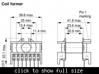
From one of the data sheets this is a mechanical drawing of a typical bobbin,


From which we can extract certain dimensions.

Ww is the available winding width.
Wh is the available winding height.
In is the mean length of a turn.
An is the available winding area assuming no margins
An! is the available winding area with margins

Ww is reduced by 8mm. The requirement is for 'creepage and clearance' in order to comply with agency isolation requirements. This is an offline converter and you do not wish to expose the end user to mains voltages. 8mm works out as being margins of 4mm either side and, with appropriate insulation, the creepage becomes 8mm.

Putting that in the spreadsheet we get,


You will see that the smaller bobbins/cores lose quite a bit of the available winding area as a result of the requirement for those margins.

And then it gets worse, sort of. You may notice that I have rounded up the number of primary turns to the next highest even number. Depending on how things go that may or may not be required. Unfortunately when operating at high frequencies there are two/three factors that have to be taken into account.

The first is that with AC currents you experience something called 'skin effect' whereby the high frequency components are constrained to flow in the outer layer of your conductor. The AC impedance, and hence losses, of the wire is greater than it would be for DC. There is also something called 'proximity' effect' whereby within a specific area between overlapped windings the field energy is minimised... I can't say I fully understand it so I'll leave it up to Lloyd Dixon of Unitrode,

https://focus.ti.com/lit/ml/slup197/slup197.pdf

Otherwise you get into the realms of 'Dowell's Curves'. It seems Snelling was involved as well. Unfortunately I no longer have the document sent to me by the helpful people at Philips..

Anyway.

Wire Tables,

**broken link removed**

and a piece of software that will do some of the sums for you,

**broken link removed**

Unfortunately the link at the bottom is 'broken'. I'm surprised the copy of the site is still there. If you are feeling brave then the .zip file is here,

**broken link removed**

It's a Delphi(4, Pascal) program that implements, in part, the equations presented in,

Fortunately Dowell and Snelling plus lots of other people have worked all of this out. I've used a paper by J.Jongsma from the Central Application Laboratory, Philips Product Division Electronics Components and Materials, Eindhoven, The Netherlands.

Electronic Applications Bulletin, Vol 35, No 3, May 1978.

Minimum-Loss Transformer Windings for Ultrasonic Frequencies. Part 1 and Part 2.

It comes with the wire table database attached and deals with both skin and proximity effect. It is a bit 'old' but it works under Wine, my excuse I use Ubuntu. I don't know whether current versions of Windows will be happy with it but it was cobbled together under WIN95 so if it moans you might have to play with the 'compatibility mode' settings.


As Dixon suggests one of the methods for reducing proximity effect is to split the primary windings to sandwich those in the secondary which effectively halves the number of layers. It also has the benefit of reducing leakage inductance, that was the third one.

Time for a break....

Genome.
 
Hi, Genome. Yea, I hope the transformer winding can be done by today because I'm going off by tomorrow evening. So, I hope I can grab some important components or equipments before leaving.

In the wire tables, I can't find details about current rating for the wire. The Cu/Dia is meaning the diameter of 1 strand of copper? As in a wire, there are many strands of copper.

---------- Post added at 14:54 ---------- Previous post was at 14:51 ----------

By the way, we are assuming that the transformer are operating at 100kHz. What if I operate at lower or higher frequency. Will it affect all our calculation?
 

Now we get to play..

As suggested I've picked the next highest even number of primary turns. That's because, and it may not be necessary, I expect to wind the primary in two layers sandwiching the secondary. The spreadsheet falls over at this time. I suppose it was really just a means of collating information and doing some simple sums. Saves finger wear on the calculator.

Otherwise 'human' intervention is required so we work through 'possible' solutions.

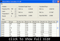
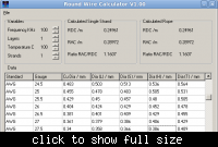
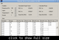
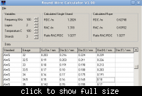
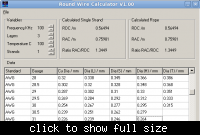
Starting at ETD29 I have Npmin as 56. With two layers that will be 28 turns per layer. The available winding width, Ww, is 11.4mm. If I use a single strand then the overall wire diameter would be 0.407mm. Using 'RoundWire Calculator Version 1.00' and hunting for a suitable bit of wire I get,


I have picked AWG 27.5, assuming you can buy it, with 'heavy insulation' and an overall diameter of 0.386mm. Depending on how 'neat' your winding capabilities are, or those of the people who are going to make the transformer, you need to take into account the possibility that things will not lay properly.

As a quick 'panic' check the available winding height, Wh, which in this case is 4.85mm. Given two layers then we have, nominally, used up 0.772mm of that winding height so things are looking embarrassingly good.

Now revert to Spice. Ooops.. may as well plug the Al values into the spreadsheet along with Lpri and Lsec values.


The Al values, robbed from the data sheets, are nano-henries per root turn for un-gapped core sets using N87 material. Lpri is Npmin^2*Al and Lsec is Npri/Nr^2 with Nr being the target turns ratio of 5.2 to 1. The tools are available so why not?

In part the primary will be composed of the output current, scaled by the turns ratio and ripple current in its own inductance so it might be good see what the overall current will be.

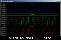
Going off on a tangent you can get some really interesting and insightful waveforms out of Spice.. This is my model set up with the values for an ETD29 core ignoring winding resistance.


VOUT, at the top, is in regulation. IRsns, at the bottom is as you might expect. ILpri tells a tale. The 'step' at switch turn on is reflected secondary inductor current. The 'ramp' is dI/dT in the secondary inductor current plus magnetising current in the primary inductance.

After switch turn off the output inductor current 'disappears' but you can see the magnetising current in the primary inductance being reset.

Perhaps I should 'go get a life' but for the moment I am going for another break.

Genome.

---------- Post added at 14:57 ---------- Previous post was at 14:52 ----------

Ooops we ran out of time, My fault.

Perhaps, if I get there, I can source the bits and have them delivered to you?

Genome.
 
Back again....

Just spotted a 'deliberate' mistake. I've been reading the Power loss Y axis incorrectly which has lead me to overestimate some of the allowable flux excursions :oops:


Back to the ETD29. This time 84 turns with a winding width of 11.4mm with 2 layers and 42 turns per layer gives me a wire diameter of 0.271mm.


AWG30 with an AC resistance of 0.583 ohms per metre. 84 turns with MLT of 52.8mm gives 4.44m and a resistance of 2.58 ohms. Spice says RMS primary current is 261mA which I will assume is entirely AC at 100KHz. That gives the primary winding power loss as 176mW.

Hmmm. So far the winding height is about 0.6mm with 4.5mm available and I am dissipating 0.176W of an available 0.714W. It turns out that this core/bobbin is in fact too large.. Time to eat humble pie and go and look at how the EFD range of cores might perform..

:oops::oops:

**broken link removed**

New spreadsheet,


Obviously for the EFD10 and EFD15 the margins render solutions impossible.

Trying the EFD30. Two layers with 41 turns per layer and 12.10mm winding width gives a wire diameter of 0.295mm. This would be AWG30.5 with a diameter of 0.279mm and AC resistance of 0.525 ohms/metre. MLT is 56.7mm so the winding resistance is 2.44 ohms. Spice says 264mA RMS so power loss would be 170mW.

Winding height is 0.558mm versus 2.58mm. Power loss is 0.17W versus 0.8. Still looking too big.

Trying the EFD25. Two layers with 45 turns per layer and 8.40mm winding width gives a wire diameter of 0.187mm. This would be AWG34.5 with a diameter of 0.18mm and AC resistance of 1.29 ohms/metre. MLT is 50mm so the winding resistance is 5.8 ohms. Spice says 259mA RMS so power loss would be 389mW.

Winding height is 0.36mm versus 2.45mm. Power loss is 0.39W versus 0.67W. Looking tight on power given the secondary will be dissipating similar levels. However there does seem to be space available so we will try a 'rope' of 3xAWG34.5 this will effectively double the diameter of the wire and we will have to move to four layers..


3 strands of AWG34.5. Since we are sandwiching the secondary the effective number of layers is 2. AC resistance of the rope is 0.439 ohms. This will be four layers at 23 turns per layer, 92 total. Winding resistance is 2.01 ohms so power loss is 134mW..

Or 1 strand of AWG28.5 AC resistance 0.466 ohms/meter. Winding resistance is 2.14 ohms so power loss is 144mW.. Wire diameter is 0.348mm so winding height will be 1.39mm versus 2.45. Power loss is 0.14W versus 0.66W.

Unfortunately this will probably not leave space for the secondary, or auxiliaries, especially when inter-winding insulation is included.

Let's ignore interleaving and try 3 layers at 30 turns per layer. AWG31 OD 0.264mm. RAC 0.76 ohms per meter. Winding resistance is 3.42 ohms. Power loss is 230mW...


Winding height 0.79mm versus 2.45. Power loss 0.23W versus 0.67W. Begins to look reasonable.

So primary is 90 turns AWG31 3 layers at 30 turns per layer. Turns ratio is 5.2:1 so the secondary requires 17.3 turns and we'll call that 18. Use a single layer of AWG27 OD 0.406. RAC is 0.267 ohms per metre. Secondary winding resistance is 0.24 ohms. Spice says the RMS current is 1.215A so power loss will be 350mW.

Winding height 1.2mm versus 2.45mm. Power loss 0.58W versus 0.67W.

Then we need some auxiliary supplies. I'm going to use 'flyback' from the transformer to generate these. With 250V minimum input and looking for approximately 15V they would work out to be 6 turns each.

After all that it would seem that your original choice of an EFD25 core was in fact workable. Makes me look a bit dumb but I suppose it is something I should be used to by now..

Core EFD25 N87 with bobbin and clips. Wire AWG31 and AWG27. 4mm margin tape. Polyester insulating tape.

Instructions and drawings to follow.

Genome.

Do we want 'screens'? mumble mumble.
 
Last edited:
Thanks, Genome. What kind of 4mm margin tape? Can I use PVC tape?

This is the ETD25 but I think they are selling separately. Which one do I need other than B66421GX187, B66422W1010D1 and B66422B2000X ?
**broken link removed**

---------- Post added at 07:04 ---------- Previous post was at 06:10 ----------

I have tried to find the wires but my place seems like they are not selling with those wire sizes. Most of the wires have a lot of strands. I will try to keep looking.
 
Last edited:

I have tried to find the wires but my place seems like they are not selling with those wire sizes. Most of the wires have a lot of strands.
Sounds like you are not looking for the correct wire type ("magnet wire"). A place where you can usually get magnet wire, apart from catalog distributors, is a motor repair shop. They mostly have the dark brown high temperature version. It can't be soldered without scratching off the isolation thoroughly.
 

Yes, those look like the parts you need.

B66421GX187
B66422W1010D1
B66422B2000X

It looks like the minimum order quantity for the cores [set] and bobbins is 5 with a minimum order quantity of 10 for the clips. We'll have to use one of them to make your output inductor. Unfortunately it means you will end up with three spare. Of course you might get annoyed fiddling about with them and take a hammer to a few..:twisted:

Tapes..... It is always a problem getting bits for this sort of stuff unless you know a friendly local manufacturer or distributor.

You really want dimensionally accurate widths and the proper materials. I'm afraid my mechanical drawing skills are not up to much and I'm just 'learning' the program but here is the beginnings of a picture,


This just shows the primary at the moment. The margins are the hatched areas. As suggested you can see you lose quite a lot of the available winding area as a result of needing them.

For general insulation you use this stuff,

**broken link removed**

It's polyester, rubber adhesive rated to 130C, 0.06mm thick. You will see from the picture that there are three layers of that across the full width of the bobbin covering the primary. Ideally you would also want some 8.4mm wide tape as well to consolidate each winding layer. Again in the picture you will see that in place.

Unfortunately RS does not sell 16.4mm or 8.4mm widths. :-(

Margin tape is generally thicker but of similar material, polyester, and temperature rating used to build up those areas. You do not really want to be winding 20 turns of tape when 6 or less might do.

PVC is a bit of a non-starter. It is not dimensionally stable and won't have the required temperature rating or possibly dielectric strength.

Genome.

---------- Post added at 07:04 ---------- Previous post was at 06:36 ----------

Sorry, just caught your edit.

As FvM says you want what is known as 'magnet' or 'enamelled' coper wire although these days it is commonly insulated with polyurethane. Don't know if this link will work,

**broken link removed**

Unfortunately RS has a limited range and given you might only be using 10 meters of the stuff it seems like a bit of an expense. As I suggest if you can find a friendly local manufacturer then things might be easier.. Erm. Rather than using 'exacts', since nothing is, what we can try doing is 'fudging' the design so it is based on a single wire diameter and build up as required using 'ropes'. Does your university have such wire 'lying around' and if so what is available?

Genome.
 
Thanks Genome.
I tried to find the copper but it seems like quite hard to get it. So, while waiting, I will test my PIC pulses and the mosfet switching.

For the regulation, may I know what is PSNS and DRV?
For the VCC, can I use 12V?
 
Last edited:

PSNS is from the top of the primary side current sense resistor, source of the bottom mosfet. DRV is to the input of your IR2131. Setting VCC to 12V should work but if your model for the UC384X properly implements the under voltage lockout..


You have to bring VCC above the 'Start Threshold' before the IC begins to operate and maintain it above the 'Minimum operating voltage' once it has started.

I don't know if you can find a similar site or source in Malaysia but a hunt for 'magnet wire' on Google found me this one in the UK,

wires.co.uk - specialist in craft wire, knitted craft wire, silver wire, enamelled copper, resistance wires, stainless steel, plated wires and many more!
wires.co.uk : Enamelled Copper Wire
WIRES.CO.UK 0.190mm to 0.280mm Solderable Enamelled Copper Wire

They appear to be part of a 'craft' site. It still seems 'expensive' but at least they will sell in 50g units rather than 500g. Perhaps you will be able to find something similar closer to home.

Genome.

---------- Post added at 06:58 ---------- Previous post was at 06:17 ----------

Oh, picture of transformer..


There is still a lot of wasted space so although the dissipation works out I might have to go and re-dimension the windings to make better use of what is available.

Genome.
 
I'm using UC3845...So, how much do I need? Sorry, Genome. I don't really understand the table as in there are many voltages..
Now, I'm testing my PIC. Everything is good.
My transformer will be delivered to my place by next week. Hopefully, everything will go smoothly.
 
Last edited:

I would like to ask, how to obtain the component values from the regulator circuit?

For the transformer winding, can I use the copper core inside the electrical wire?

---------- Post added at 02:55 ---------- Previous post was at 02:47 ----------

I plan to run both circuit at 20kHz. So, I just need to change RT and CT only?
 

can I use the copper core inside the electrical wire?
No, the adjacent windings need to be insulated against each other. Transformers are usually wound from enamelled wire, also called "magnet wire". For large power transformers, sometimes bare copper rods are wrapped by paper tape or foil. But it's not a convenient method for a small transformer, I think.
 
Status
Not open for further replies.

Similar threads

Part and Inventory Search

Welcome to EDABoard.com

Sponsor

Back
Top