Continue to Site

Welcome to EDAboard.com

Welcome to our site! EDAboard.com is an international Electronics Discussion Forum focused on EDA software, circuits, schematics, books, theory, papers, asic, pld, 8051, DSP, Network, RF, Analog Design, PCB, Service Manuals... and a whole lot more! To participate you need to register. Registration is free. Click here to register now.

Fluctuating voltage from a bad transistor

Status
Not open for further replies.
Thanks for your info.

PNP transistors can be used for all the same things as NPN transistors - amplifiers, oscillators, constant current sources etc.
PNP transistors work exactly the same as NPN transistors, except the voltages are reversed.

Yes true, but why would a designer use a PNP transistor if it does the same thing as a NPN?

What have you seen PNP transistors used for

For me I have seen this:
1.) to invert a positive DC voltage INPUT on the base to a negative DC voltage OUTPUT on the collector
2.) to invert a HIGH logic to a Low Logic

I know i have seen PNP transistors in a push pull output stage

But I have seen PNP transistors used a inverters or when used as a Negative logic switch?
 

I know i have seen PNP transistors in a push pull output stage

That is a good example. Most circuits (except very simple ones) use NPN and PNP transistors.


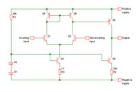
Here is a simple opamp circuit:


Q1 and Q2 are NPN transistors that make a differential pair.
Q4 and Q9 are NPN transistors used as current sources.
Q5 and Q6 are PNP transistors that make a current mirror.
Q8 is a PNP transistor used as a common-emitter gain stage.


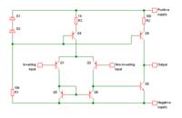
But we can also turn the whole circuit upside down and swap the PNP and NPN transistors, so it looks like this:


Now the differential pair and current sources are made with PNP transistors, and the current mirror and common-emitter gain stage are made with NPN transistors.
 

danny davis, with the greatest of respect, you clearly have no idea of how transistors work. I suggest that before looking for faults you get to grips with the basic transistor construction, learn about PN junctions, biasing circuits and the different ways of connecting transistors to make them perform in different ways.

Brian.
 

Why did they use this PNP transistor? and not a NPN transistor? and will the base to emitter measure 0.7 volts?

PNP pic#1.jpg

Here is a couple more NPN transistor, will the base to emitter measure 0.7 volts?

NPN pic#1.jpg
NPN pic#2.jpg
 

The answer is: It can't be seen from the schmematics snippets you are posting. You need to understand the purpose and overall function of the circuit to analyze the details.

Apparently not all transistors and diodes in the circuit are continuously in active mode, thus not all will expose a forward bias voltage of 0.7V. This must be also supplemented as a resevation to the discussion in post #17 to #20, which only applies to transistors in active mode, e.g. linear amplifiers.

To illustrate the point, take a look at Q2. It's base-emitter voltage is zero unless an AC voltage will be coupled to the base via C19. The AC voltage will be rectified and forward bias the base-emitter junction during the positive halfwave. If the AC voltage has about 50% duty cycle, e.g. a sine voltage, the average base-emitter voltage that can be measured with a voltmeter will be still around zero.
 

It's base-emitter voltage is zero unless an AC voltage will be coupled to the base via C19.

What state or mode is this transistor in? since it needs an input signal to turn it on and forward bias the base - emitter?

The transistor is off , not active , zero volts across base to emitter, no .7 volts

The input AC voltage will make the transistor active and turn on but it will still measure zero volts across the base to emitter right?
 

That's right for Q2, it's less easy to determine wheter other transistors have a permanent bias or not.

Comparing with a known working device and annotating the schematic with expectable voltage levels might help.
 

for Q2, it's less easy to determine whether other transistors have a permanent bias or not.

If a transistor is not permanent bias , it gets forward biased , active, turns on, energized from an input signal

Is the transistor a switch? or amplifier?
 

How can it be both?

Permanent bias
0.7 volts from base to emitter as an amplifier
0.7 volts from base to emitter as a transistor switch?

Not Permanent bias
0 volts from base to emitter as a transistor amplifier
0 volts from base to emitter as a transistor switch
** Only gets forward biased 0.7 volts, active, turns on, energized the transistor from an input signal?

What is this called when the transistor is not forward bias except when the input signal is applied?
 

Transistor controlling the current?
Transistor#1.jpg

Transistor as a comparator? or a switch
NPN pic#1.jpg

Transistor as a comparator? or a switch
NPN pic#2.jpg


Why did the designer use transistors instead of a FET?

Using a transistor as a switch is different than using a FET as a switch? what is the difference?
 

I also see Diodes from the base of a transistor , going to ground

The Diodes on the base going to ground protects it from negative voltage? what does that mean, because a diode is only 0.5 volts so it any negative voltage will be much more than 0.5 volts but it will conductor the transistor if the diode wasn't there.

They put the diodes on the base going to ground , so negative voltage won't turn on the transistor?
 

Therefore the diode is added so that the base does not get a negative voltage that would damage it.

But the diode only protects the transistor , of how many negative volts? the diode is only 0.5 volts, so is the negative voltage is more than -1 volts it will damage the transistor because the protection diode is only 0.5 volts to turn it on

Any negative voltage more than 0.5 volts will turn on the protection diode?
 

A silicon diode normally conducts with about 0.7V. It is 0.5V when it is hot and when its current is very low. It is 1V when it is cold and when its current is very high.
When the diode conducts at -0.7V then it protects the emitter-base from having a higher negative base voltage.
The emitter-base breaks down and is damaged when the base voltage is -5V or more negative.
 

Therefore the diode is added so that the base does not get a negative voltage that would damage it.
Which statement are you quoting? You are the only one how talked about protection diodes.

In fact the said circuit is a rectifier rather than a protection means.

As a general suggestion: Horowitz, The Art of Electronics, start with
Chapter 1 Foundations
Chapter 2 Transistors
 

No the diode protects the base from negative voltage
You can see it like this. But it's not the diode's primary purpose in this circuit.

By the way, if you already mean to understand the circuit's operation, why are you asking?
 

Im not sure how much negative voltage the diode protects
The maximum allowed negative voltage on the base of the NPN transistor is about -5V. The diode begins to conduct a low current and clamps the voltage to -0.5V, conducts a medium current and clamps at -0.7V and conducts a high current and clamps at 1V.
 

Status
Not open for further replies.

Part and Inventory Search

Welcome to EDABoard.com

Sponsor

Back
Top