Continue to Site

Welcome to EDAboard.com

Welcome to our site! EDAboard.com is an international Electronics Discussion Forum focused on EDA software, circuits, schematics, books, theory, papers, asic, pld, 8051, DSP, Network, RF, Analog Design, PCB, Service Manuals... and a whole lot more! To participate you need to register. Registration is free. Click here to register now.

fixing design for simultanios excitation of a sequencer

yefj

Advanced Member level 4
Joined
Sep 12, 2019
Messages
1,412
Helped
1
Reputation
2
Reaction score
5
Trophy points
38
Activity points
8,604
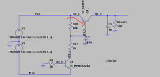
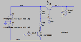
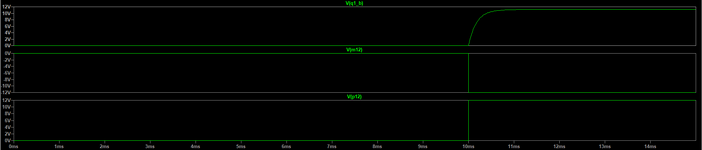
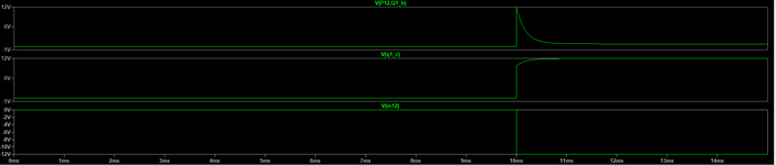
Hello,The circuit is supposed to delay the output of P12 because the PNP is opening gradually.
In previos version it worked great but i put P12 as a pulse and circuit just not working.
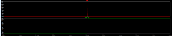
The Veb is totally different.Veb is supposed to be 0 and rise gradually.
But when i made P12 0-12V pulse my Veb is tottaly ruined.
How can i fix it so Veb will rise gradually from 0 till PNP is opening?
LTSPICE file is attached.
Thanks.
 

Attachments

  • 1.PNG
    1.PNG
    10.7 KB · Views: 16
  • 2.PNG
    2.PNG
    12.6 KB · Views: 11
  • 3.PNG
    3.PNG
    11 KB · Views: 11
  • test4.zip
    4.7 KB · Views: 7
Last edited:
UPDATE:
Hello , What about the situation when i move C4 to be parralel to R10.
There is a basic law regarding capacitors shown below.
"The principle of continuity of capacitive voltage says: In the absence of infinite current, the voltage across a capacitor cannot change instantaneously."

looking at the following situation how does the capacitor acts?
one leg feel rise of zero to 12V what does the other leg get because of that and why?
1726693470410.png
 
Hello Brad , So in the original case C4 was directly charged by P12 and it charges very fast.
In the upgraded version there is no pass to the ground from the base .
What what is physically happening to the capacitor
We have a capacitor in parallel to R10, a pulse is coming .
How it will react? It will start charging .
What is the difference of charging in the first and second case?
When pulse comes Veb is not 12 automatically .
why in the second case C4 is charged slower?
Thanks .
C4 now charges and/or discharges through the resistor network... an RC time constant can come into play.

C4 now succeeds in holding Q1 Off at power-up, because it conveys positive voltage to the PNP's base. The situation changes as C4 charges.
 
Hello Brad,As you can see below C4 charge current is much much less then sitatuon 1.
Can you see the logic in the current plot ?
at first the current rises to 20mA then at some point there is a very sharp drop in the current exacrly then the base voltage starts to be 11.2V.
What causes this current behavior?
"C4 now succeeds in holding Q1 Off at power-up, because it conveys positive voltage to the PNP's base. The situation changes as C4 charges."
LTspice file is attached.
situation 2:
1726742174776.png


1726742329469.png
 

Attachments

  • 1726738284815.png
    1726738284815.png
    17.3 KB · Views: 1
  • 1726740845882.png
    1726740845882.png
    22.3 KB · Views: 1
  • new.rar
    4.3 KB · Views: 1
Several design flaws:

1. No design specs for tolerances Tr, Tf on P21 nor Td +/- , Tr, Tf, & Iout.
2. No R series controlled current limit on Veb of Q2. Power on applies >10V across Veb on start.
3. No protection of Veb from excessive reverse voltage{>-5V} from contact bounce if any (?)
4. There is no current limiting series R other than PNP-Reb + ESR (C4)
--- Updated ---

Also in spite of occasional datasheet flaws. [nS] is nano-Siemens, while [ns] is the only correct abbreviation for nanosecond.

Simultaneous ends in “ous”
 
Last edited:
Can you see the logic in the current plot ?
at first the current rises to 20mA then at some point there is a very sharp drop in the current exacrly then the base voltage starts to be 11.2V.
The principle underlying all this revising... is the behavior of a PNP. Textbooks cheerfully tell us it's the opposite of NPN. However PNP is less familiar, less intuitive. The polarities and bias method require a different format when operating a PNP.

Likewise the technique of putting a time-delay capacitor in the bias wire. You're gravitating toward the correct arrangement although there's still more optimizing to be done. Adding a resistor here, removing (or altering) a resistor there.
 

LaTeX Commands Quick-Menu:

Similar threads

Part and Inventory Search

Welcome to EDABoard.com

Sponsor

Back
Top