Continue to Site

Welcome to EDAboard.com

Welcome to our site! EDAboard.com is an international Electronics Discussion Forum focused on EDA software, circuits, schematics, books, theory, papers, asic, pld, 8051, DSP, Network, RF, Analog Design, PCB, Service Manuals... and a whole lot more! To participate you need to register. Registration is free. Click here to register now.

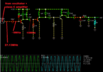
27 MHz Amplification Query

Status
Not open for further replies.
Just a guess - you have the two 2.2uH inductors parallel to each other, you could be seeing the second transistor oscillate as well as the first one. Think of them as primary and secondary of a transformer. What happens if you rotate one of them 90 degrees, does the output change?

Brian.
 

okay wait a second sir........ let me try!

- - - Updated - - -

On the collector of the 2nd transistor its again 4.50MHz and on the base of the 2nd transistor its about 10.9MHz with that 1K ohm resistor in series with the 2.2uH inductor at the collector of 1st transistor...... same readings with a 90-deg shift in position of the second 2.2uH inductor!
 

27 MHz Oscillation issues

I really want to throw this circuit in the bin now! nothing seems to work....... could it be that my transistors are faulty?? :bang:

- - - Updated - - -

and what could have been wrong with the construction???? :evil:

- - - Updated - - -

Uff....... I built it again on a veroboard but this time no PA stages or the TX-2B circuit....... only the oscillator with another stage of amplifier having biasing of 33kohm resistor on power rail and another with ground having both their common terminals with the base of 2nd transistor....... I connected only 2.2uH inductor without any parallel capacitor with it on the collector of the 1st transistor...... its working! I counted 27.13MHz on the collector of the 2nd transistor........ Crystal was at the base-collector junction of the 1st transistor!

Thanks for the help everyone and plz do continue to guide me........

I still wonder why is it not giving me desired output in the previous circuit???
 
Last edited:

RF is a strange animal and oscillators are a strange sub species. You are not alone with these problems, you can see why we often go to extreme lengths to filter supply lines and screen all the sections from each other to avoid any risk of something going wrong. Even then things don't always work as predicted. I think there is a 'gut feeling' element to RF designing as well as a theoretical aproach, something you learn from experience not text books.

Brian.
 
  • Like
Reactions: RMMK

    RMMK

    Points: 2
    Helpful Answer Positive Rating
but the weirdest part is the previous circuit was on a PCB i printed so painstakingly! :laugh:
 

Another weird thing just happened........ i dont know why and how but when i removed and then re-soldered the components in the previously not running circuit whose picture is shown below (I have also posted the pic previously); its somehow now delivering 27.131MHz count at the 2nd transistor collector! I havent connected the PA stages as of yet apart from the 2nd transistor stage with the oscillator! :bang:
 

hahahaha........ Sir I watched Gremlins recently....... it was a nice comedy-cum-horror! :oops:
I will next work on the PA stages and then after they get completed will start on the receiver! I will share the results and ask for the expert opinions in the meantime....
Thanks!
 

While designing the transmitter, you'll want to consider how to transmit commands.

AM is the easiest.

Do you know whether to have the carrier on most of the time, or have it off most of the time?

My Futaba transmitter had the carrier on most of the time. Commands were sent by turning it off for 1-2 milliseconds.

First was the announce gap. Then 4 command gaps in quick succession. Five gaps in all. Fifty times per second.

Then it is a question whether to (a) turn your oscillator on and off suddenly, or (b) disconnect and reconnect it to the antenna.

well i suppose sir that this circuit i built remains off until a signal of certain kilohertz from TX-2 IC come into creating a bias at the second transistor for necessary amplification! am i right?
Is it the better way to send commands or the other way around of having it on all the time and getting it off for sending commands........? How would that be done??
 

If the battery in the transmitter can stand it, it is best to leave the transmitter on. This is so any AGC in the receiver turns the receivers gain low, so it does not pick up spurious signals. If the transmitters is off for more then a second or so the receiver would wind its gain up to maximum and try to receive signals from around the world, one of which may actuate your decoding circuits and cause something to happen!!
Frank
 

I checked on the PA stages and they are showing different frequency counts. somewhere between 10-15MHz. Interestingly the final stage of 2N3866 was not even coupled to the rest but still showed some 9MHz....... I think there may be some kind of coupling going on in the PA stages..... whenever i make my finger touch the transistors; the freq values changes some 1-2MHz from the previous readings.
Plz help.... I will try to upload the current circuit diagram of the whole circuit and my circuit pic asap!
 

Untitled.png
My choice of transistors is : 2N2222, 2N2219A, 2N3866 (in the order as shown in the above pic)
the simulation shows that the DC volatge source is providing 25Amps @ 12Volts..... Isnt it too much??

- - - Updated - - -

but its not working in actual!
 
Last edited:

Starting at the output. If your PI network has equal caps, if it is resonating its reflecting 50 ohms back to the PA. The caps look too big in value to me. If 1µH resonate with 27 PF in the early stages, why have you got 5.8µH and 27 pF in the PA?
Frank
 

Starting at the output. If your PI network has equal caps, if it is resonating its reflecting 50 ohms back to the PA. The caps look too big in value to me. If 1µH resonate with 27 PF in the early stages, why have you got 5.8µH and 27 pF in the PA?
Frank

Ah! I was short of 1uH inductors...... therefore I had to use the 5.6uH one! Also the 5.6uH inductor make was such that it provided me a 90-deg sweep from the other inductors which i thought may inhibit any coupling!

- - - Updated - - -

I computed the pi-netwrok values from here:-
**broken link removed**
 

001.png
As shown above; when 27MHz signal goes into the next stage I get a count of some 15MHz in the actual circuit at the collector of that transistor! I tried removing the 27p capacitor but no changes occur apart from a little increase to some 16.5MHz. Also I have disconnected the next all the stages from the 12volt rail and from the input...assuming some coupling would have occurred..... help!

- - - Updated - - -

when i placed my multimeter probes set at VDC.... across base-emitter of the transistor; i could measure only 0.12Volts...... is the biasing problem? when i placed a 68Kohm resistor across the base-ground; it didnt work as well!
 

For tuned amplifier it is expected to have collector tank tuned to 27MHz. You have first two tuned to 30MHZ and last to 12MHz.
Last two stages are C class amplifiers which may show "incorrect" base voltages. This is because transistor operates like a switch for RF voltage present on base.
DC voltage on base of transistors you must measure with 10uH-100uH inductor in series with positive probe not to introduce probe parasitic capacitance into a circuit.
 

well i replaced the 27pF in the first stage with 30pF and the 1uH inductor with 1.2uH but to nothing changed! I am still reading somewhere around 15-16MHz.......
 

Are you testing real circuit or just trying to simulate it? Spice is good for linear circuits and not for nonlinear such C class amplifier is.
If you are measuring frequency with counter as something arround 15-16MHz than suspect your 27MHz generator or oscillations in amplifier.
As a joke it happens in electronic that oscillators do not oscillate always but amplifiers often do.
 

I am working on a real circuit sir....

- - - Updated - - -

the oscillator is working...... at the collector of the previous stage i am getting a count of 27.13MHz...... after the capacitor of 100pF its getting dropped and then on the collector of this transistor (that is the first transistor in the below pic) its a static 15.60MHz........
001.png

I have shown the next stages disconnected from the 1st stage because i disconnected them in the actual circuit...... i thought there might be some coupling!

- - - Updated - - -

I placed a 10uH inductor in b/w the +ve multimeter probe and the base of the first transistor in the above pic and the -ve probe of the emitter of the same transistor....... measured some 0.9Volts! It seems like it is correctly biased! I understand that the this stage is oscillating incorrectly but how am i gonna inhibit it??
 

Status
Not open for further replies.

Part and Inventory Search

Welcome to EDABoard.com

Sponsor

Back
Top