Continue to Site

Welcome to EDAboard.com

Welcome to our site! EDAboard.com is an international Electronics Discussion Forum focused on EDA software, circuits, schematics, books, theory, papers, asic, pld, 8051, DSP, Network, RF, Analog Design, PCB, Service Manuals... and a whole lot more! To participate you need to register. Registration is free. Click here to register now.

[SOLVED] How many LEDS Off a 555

Status
Not open for further replies.
Ive been looking at that :)

- - - Updated - - -

Well i have made the circuit in Proteus and it works fine.

Ive followed the example from SunnySkyguy.

Now i need the parts :). I guess the tricky party is wiring the LEDS as letters


I wish you turned off the grid and grey background on your schematic.
It is missing LED part numbers for us to see the range of forward voltage and maximum allowed continuous current.
It is missing a supply voltage.
You have LEDs directly in parallel which is not correct unless you buy thousands then test and sort them all into groups with exactly the same forward voltage.
 
Not only that, if you are using a NPN transistor the Emitter goes directly to ground. If there is a current limiting resistor it goes between the load and VCC rail, never between the emitter and GND.
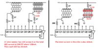
 
Oh, I didn't know I could do that!!.

I've just copied the example circuit into Proteus a with the 555 timer.

I assumed this was correct :-s.

Okay I'll remove the resistor and take the emitter straight to ground.

Obviously my IQ is not as high as yours :).

I'm still learning, I've only been into electronics for 6 months
 

Hi Englewood!

Have a look at the schematic I've attached, if you can. It's a pdf as the image is much cleaner and neater in this format.

The resistor into the base of the transistor is not so necessary as the 4017 only outputs about 8mA current, but it won't hurt your circuit or the transistor.
The resistor from the base of the NPN to 0V (-V/GND/the return path/whatever people choose to call it) is to anchor it to a logic level when it is off (it prevents it accidentally turning on).

Apart from pin 11 connecting to pin 15, as you have done, the capacitor and the resistor in the schematic which also connect to pin 15 of the 4017 stop it randomly going through its outputs when you power the circuit up (that can be very annoying or bad depending on what the counter has to do) - it is called a power-up reset. There are lots of ways of doing this, this one works for me, I use a 1K resistor and a 0.33uF (PET dielectric, but any will do) capacitor.

Some people put the LED current limiting resistor from 0V to the LED, some put it from +V to the LED, it makes no difference, but do use a resistor for each string. One is enough for each string of parallel LEDS, because - as you know - paralleled resistors values are divided by how many are paralleled.

An astable 555 (maybe better than a one-shot/monostable) connected to the 4017 how you have it (with pin 11 output into reset pin 15) will run through the letters for you and will go on/loop for as long as the circuit is powered.

View attachment LED letter circuit - Schematic.pdf


Oh, you already have the astable 555 in your schematic, my apologies, didn't see the upper resistor!

:)
 
Note that your choice of a Darlington NPN changes things as it has an extra diode drop.
This may be better suited to a 12V supply using a different Array instead of the 2S5P config consider for red 5x2V if possible, i.e. 5S2P

We need to know the Colour of LED and then the source of LEDs as voltage drop can vary.
R/Y ~= 2.0~2.2V ( lower are usually better )
B/G/W ~= 3.0-3.4V
 
Not only that, if you are using a NPN transistor the Emitter goes directly to ground. If there is a current limiting resistor it goes between the load and VCC rail, never between the emitter and GND.
No. Since the output voltage from the Cmos digital IC goes almost as high as the positive supply then it makes no difference if the current-limiting resistor is at the load or at the emitter.
 
Not only that, if you are using a NPN transistor the Emitter goes directly to ground. If there is a current limiting resistor it goes between the load and VCC rail, never between the emitter and GND.


THe advantage in my configuration has one additional purpose, it raises input impedance and limits load current.

Ib limit as CMOS load= hFE*Re
 
But hFE is not used for a saturated switching transistor. The base current should be about 1/10th or 1/20th the collector current for a little low current transistor.
 
No. Since the output voltage from the Cmos digital IC goes almost as high as the positive supply then it makes no difference if the current-limiting resistor is at the load or at the emitter.

There are a couple of different scenarions, the OP should be aware that perhaps I havent clarified.

For operation in saturation region, resistors on the collector are used when transistors are paralleled for current sharing and even then a low value, just to accomodate the different saturation voltage of the devices.

If the aim was to make a current source with the transistor then an increase in VRE would achieve just that, by lowering the base current, so the resistor on the emitter would be beneficial. Its just in this case its a good practice to put a limiting resistor in each string of series LED's instead to ensure the current is effectivelly shared and that works best on the colector or before the VCC rail that it does on the emitter, with the current schematic, because contary to the original circuit (where IE ~ ILED) he has more than one LED.

Then there's always the remote possibility he wishes to use a mosfet in future and the loss in VRE would perhaps make VGE too low to reach saturation. So better to design the circuit in a way that can accomodate for both.
 
Last edited:
Don't know if I'm missing a few things here, and the recent few posts and exchange of ideas in this discussion are genuinely very interesting, one reason it's worth coming to edaboard to learn and share ideas...

...but in the image posted discussing where the resistor can be placed it shows a counter with an active low reset, is Englewood actually using an active low reset counter? (Are you?)

The CD4017s I've used are all active high for reset, and his/her schematic doesn't explicitly show an active low device.

Might be an idea for some-one to clarify this point, as (without meaning to be rude, I also have loads to learn myself - all those things which can be confusing at times; meaning the bombardment of minimum necessary knowledge about each device in hand and how electricity works, etc., for a circuit to work), our friend seems to be on a learning curve in general, might not know about active high/active low/edge-triggered and whatever, who knows... so maybe the less confusing the better.

And where's the Darlington - is that the BC517 he/she said they had earlier in the thread? the last schematic I saw by him/her had a 2N2222A transistor - that works.
 
Good point. The not gate on the reset is not doing anything there. Reset is active high.
Now that I look at it, there is also other typo. The current draw is calculated for a single LED voltage drop, but the schematic shows two in series, so the currents are likely wrong. 0.2V is also a very optimistic saturation voltage, unless the transistor base is being grossly overdriven.

Assuming that configuration with 100mA the 2n2222 datasheet shows:

https://www.google.co.uk/url?url=ht...AOSCVg&usg=AFQjCNHYQ4oYxDtdLgr2SyGrwdTTogl1sw

... that for a VC of 1V and a current of 150mA the gain is minimun 150. That means a current of 1mA on the base is enough to place the transistor in saturation for the LED's current and perform some crude current limiting in case of short circuit to roughly 300mA (gain = 150...300).

So a Darlington would apparently not be needed.
 

Right lets get a few things straight!.

I was put on a BTEC level 3 course by work with very little electronic experience, they just wanted me to fault find componets really.

The course wasnt very good, home study and very poor i thought ICS course it was.

I passed the course somehow.

Then i thought i need to learn more basic electronics to get more of a understanding, so i decided to build a few things.

The aim of my project is to make a Word (Englewood or Euroteck) flash across from E - D and repeat it self at a certain speed.

Idealy i would like lets say EURO to flash in WHITE and TECK to flash in BLUE.

I will be using a
9v-24v supply
555 timer (NEW ONE)
CD4017 Decade Counter
BC517 Transitors (As i have some lying around)
White LEDS
Blue LEDS
Ive worked out that the biggest letter will be 12 LEDS

As for the Proteus shematic i have produced, im new to the software also but im learning and it takes time to learn.

Im not sure if the decade counter is Active High or Active low (Which i do understand but how do i tell the difference in proteus)

Proteus didnt have a BC517 so i used a 2N2222 for an example.

Some mistakes here i presume.

The LED fV of each LED was set to 2.2V
The mA was 10mA

D123

Thank you for your Schematic :).

Im a HE (Well on th outside) :)
 
Last edited:

Englewood, don't feel bad with yourself. Some of these things you only learn with your mistakes. In electronics you will never know it all.

What I meant to say earlier is that darlingtons are not needed as they are usually more expensive, but if you already have them there is no problem in using them. The only difference is the base current is now 0.1mA, so a larger base resistor would suffice.

I am biased at using the grounded emiter as I mentioned above. The reason being you can just consider the transistor as a switch and worry about current limiting on each series branch of led's. there's no need to change base resistors or anything similar. For 9V supply you could use 2 leds in series.

Say for example 9V, assuming a voltage drop across the transistor of 1V you would be left with 8V. Take 4V from the red leds thats 4V left. Since R=U/I, if you wish to feed that branch with 10mA then the value of R would be 4/0.01A = 400Ohm. There's no such resistor so you could use 470Ohm, for example. (that would give 8.5mA).

One thing you might want to be aware with blue leds is that their voltage drop is 3V. In practice this means that the led will be brighter for the same current, so if you want the same brightness as the red you may have to reduce the current. have a try.

Back to calculations, for the blue ones the transistor is still dropping an assumed 1V, that leaves us with 8V. Take 3V from each led and you get 2V left. Again 2/0.01 = 200, with the closest standard value being 220Ohm. That would give a current of 9mA.

Using this way you make sure all the leds are protected and their brightness will be very similar even if the forward voltage drop varies.

Using the grounded emitter you can also calculate the base current very easily. Say your voltage is 9V and the outputs of the 4017 are 8V. Take another 0.7V from the VBE loss on the transistor and thats 7.3V. For a base current of 0.1mA as sugested on the datasheet thats 7.3/0.0001A = 73Kohm and there is no need to change this value when going from red to blue leds.

The rest of the circuit looks fine, altough I'm a bit unsure how you plan to change from red to blue. Is it the same display with both leds blinking alternativelly? Or finish one and blink the other? Different displays? By display I mean whatever you use to built the leds on to display the letters.
 
  • Like
Reactions: d123

    d123

    Points: 2
    Helpful Answer Positive Rating
Blue white LEDs are ~3V not 2.

Your Darlington is better choice now with 9-24V but Rs current limiting R must match supply Rc=( Vin -Vf(string total)-1V) /If (parallel total per letter) .

The gain is 1000 typ, at 100mA which means the CD4017 supply voltage (if regulated) determines the LED current using only Rc on the emitter only. Then Re=( Vcc - Vf (string tot.)-1.4V/If ( letter total)

Thus the power drop will be in each darlington and Re, permitting a wide range in Vin with a suitable LDO for Vcc on the CD4017

Reset and 4017 outputs are both high so no inverter needed to reset after last letter.
 
  • Like
Reactions: d123

    d123

    Points: 2
    Helpful Answer Positive Rating
Wow you know your stuff :).

Yes its the same display, i want EURO to flash in white letter to letter, then TECK to flash in BLUE letter to letter then back to the start
 
Last edited:

I wish you turned off the grid and grey background on your schematic.
It is missing LED part numbers for us to see the range of forward voltage and maximum allowed continuous current.
It is missing a supply voltage.
You have LEDs directly in parallel which is not correct unless you buy thousands then test and sort them all into groups with exactly the same forward voltage.

You say i have my LEDS directly in parallel, i understand what you mean by correct forward voltage because when i change the fV on the software.

IE one LED 3.6V, one LED 3.2V they didnt work. They had to be almost the same fV.

So what way do i put them?
 

Each series string of LEDs needs to have its own series current-limiting resistor with a couple of volts across it. Then if you have a string with two 3.2V LEDs and another string with two 3.6V LEDs, the resistors make their currents almost the same. Without the resistors, the LEDs with the lowest forward voltage hog all the current and soon burn out, then the string with the next lowest voltage burns out, then the next then the next.

Sunny buys expensive LEDs that are already matched to have an identical forward voltage. My cheapo Chinese LED flashlight has 24 white LEDs perfectly matched so that they are fine when connected directly in parallel.
 

Status
Not open for further replies.

Part and Inventory Search

Welcome to EDABoard.com

Sponsor

Back
Top