jagdeepsingh3@hotmail.it
Member level 3

Static IGBT losses for new part can be modelled as Vce*Ice=P=(1.25V +0.01Ω*Ice)*Ice.
Thermal Resistance is unknown for your heatsink and interface, while Rjc is only 0.27'C/W Do you have a CPU heat sink?
Is this a bipolar output with centre ground load?
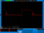
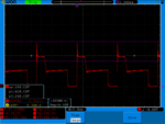
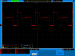
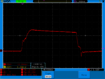
That would explain the asymmetric pulse widths to mid-level Voltage.
Drivers need to be able to transfer Gate charge ~1mJ or current limit of Ig x transition time. The test parameters used Rg=3, so driver ESR must be examined and // IGBT's factored.
ESR is usually 10x Rb for a saturated driver switch. where Rb is 330R?
Better ones are up to 50xRb, based on Vce(sat) Ic/Ib rating.
my rule of thumb is to compare impedance gain of each stage.
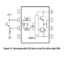
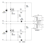
this is my refrence circuit:

this is a full project website:
http://danyk.cz/reg60v_en.html


