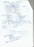
Continue to Site

Welcome to EDAboard.com

Welcome to our site! EDAboard.com is an international Electronics Discussion Forum focused on EDA software, circuits, schematics, books, theory, papers, asic, pld, 8051, DSP, Network, RF, Analog Design, PCB, Service Manuals... and a whole lot more! To participate you need to register. Registration is free. Click here to register now.

27 MHz Amplification Query

Status
Not open for further replies.
yup...... its the same transmitter!
The below is the transmitter schematic (same as before):-
schematic-transmitter (1).png
These are the pics of my construction:-
IMG_20140728_210846.jpg
IMG_20140728_210850.jpg
 
Thank you. Your construction should be OK at 27MHz. Sorry if I sounded condescending but sometimes when people say they build on Veroboard they mean they used the whole sheet and a few Km of connecting wire as well :shock:

I can't see any reason why R6 should get warm, can you check if the NE555 is working correctly by attaching a loudspeaker through a 100 Ohm resistor between ground and pin 3. If it's working properly you should hear a low pitched buzz.

The only construction comment I would make is that you shouldn't lay the two inductors parallel to each other because that gives maximum magnetic coupling between them. Ideally there should be no coupling so you could try rotating one through 90 degrees, either so it lies on the board at 90 degrees or it stands upright.

Regarding the crystal problem, personally I would change the oscillator circuit so it matched the one in the link I posted. Although it isn't technically wrong, I would be suspicious of a circuit that connected a crystal directly between the base and collector of a transistor because the crystal could be overdriven and it's loading capacitance could be wrong.

Brian.
 
  • Like
Reactions: RMMK

    RMMK

    Points: 2
    Helpful Answer Positive Rating
Thanks a lot...... I will try the mods and will share the results shortly.
 
Last edited:

Should it be like this?? Plz confirm the values of the individual components......
Image (5).jpg
Can u tell me how they select the value of Inductor at the collector? How is the Reactance is taken?
 

Should it be like this?? Plz confirm the values of the individual components......
View attachment 107845
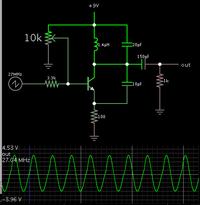
I made a simulation.

The emitter capacitor creates undesired resonant action. I believe you should leave it out.

It is vital to be able to adjust the bias. So I use a potentiometer.


I'm assuming your crystal is installed the right way. All I can use is a clock input.

Can u tell me how they select the value of Inductor at the collector? How is the Reactance is taken?

From what I have seen, it is common to make the inductor 1000 or more times the capacitor value. With a large ratio you have small current, and larger voltage swings.

If you make the inductor small, and the capacitor large, then you need more supply current to drive them.

My screenshot shows only the RF oscillator portion. I cannot be sure how much current the next stage will draw. Just as a guess I added a 1k resistor.
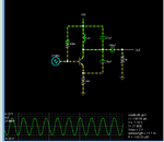
 
  • Like
Reactions: RMMK

    RMMK

    Points: 2
    Helpful Answer Positive Rating
which software is this? But I dont have 1.4uH inductor...... Can I use a 1uH and a 0.7uH inductor is parallel to make roughly around 1.7uH since the inductors i have have tolerance around 10%...... and for capacitor i can go with a 27pF capacitor or a trimmer capacitor having a range of 5pF to 20pF! Or do u think that i better procure components of the same values! What do u say?

- - - Updated - - -

and i dont have a potentiometer as well!:thinker:
 

which software is this?

Falstad's animated interactive simulator. Free to download and use at:

www.falstad.com/circuit

(Your computer needs to have Java installed.)

This link will (a) open the website, (b) load my schematic into the simulator, and (c) run it on your computer.

https://tinyurl.com/ljlade8


But I dont have 1.4uH inductor

You can make your own by winding a few loops of wire.

I've seen many radios with small coils of wires on the circuit board. The technician tunes them easily by spreading or squeezing the ends (with a plastic tool, not his fingers or a metal tool).

I was lucky when I made my 72 MHz receiver. I had a capacitor about 40 pF. I ran the formula to tell me what inductor value I needed. Then I used a calculator for air core inductors, which told me how long, and what diameter, and how many turns.

I constructed the LC tank, and watched how it responded to my transmitter signal. I pushed and pulled on the loops, changing the resonant frequency.

Sure enough, the scope trace went up and down. I was able to position the loops to obtain a peak reading, at 72 MHz.

I was lucky because my coil resonated in the range I wanted. I barely knew what I was doing. My scope only responded under 1 MHz.
 
  • Like
Reactions: RMMK

    RMMK

    Points: 2
    Helpful Answer Positive Rating
You connect inductors in series to add their values but unless coupled properly you can get all kinds of strange effects, including subtracting one from the other so I would advise against it.

The simplest 1.4uH inductor is 12 turns of wire on a 10mm air core spread over 10mm length so it's fairly easy to make one.

Brian.
 
  • Like
Reactions: RMMK

    RMMK

    Points: 2
    Helpful Answer Positive Rating
An interesting thing happened....... Firstly I think the reason of R6 getting warm was the over-supply of current. I was supplying some 10 Volts through my power supply and it seems like it had immense ripples in the waveform and the result was somehow 555 got faulty! I changed it and the transmitter again worked as it was previously! Here is the interesting thing; when i connect the transmitter to that power supply at 9 Volts and the receiver to a 5 Volt battery, the receiver receives stuff at a 1 foot (at max.) range but when i connect both the receiver and transmitter with the 5V battery; the receiver donot glows the green led which was an indication of receiving signal!
Last night i dont know how but for a moment of time i did get a reception range of 16 ft......
I am in process of building the transmitter again with the updated circuit diagram (as shown in the simulation). i will share the results as soon as i build it.
 

You connect inductors in series to add their values but unless coupled properly you can get all kinds of strange effects, including subtracting one from the other so I would advise against it.

The simplest 1.4uH inductor is 12 turns of wire on a 10mm air core spread over 10mm length so it's fairly easy to make one.

Brian.

I built the circuit as was stated and it didnt work........ worse the whole circuit heated up like there was a heater connected! I connected both the transmitter and receiver with independent 5 Volt/ 1Amp batteries and the receiver part worked as it has been working! But the moment i tried connecting the transmitter; sparks were generated from the terminals and the whole negative wire heated up! I just pray the components didnt got fried! Plz help...... One thing I must tell u that i couldnt find a 20pF capacitor so i ended up using a 27pF capacitor and built a inductor at around 1.0uH with bare wire (Dimensions:- Dia. = 0.5-inches; Length = 1.5-inches and N= 16)! Inductor wires are not touching each other.

- - - Updated - - -

I made a simulation.


From what I have seen, it is common to make the inductor 1000 or more times the capacitor value. With a large ratio you have small current, and larger voltage swings.

My screenshot shows only the RF oscillator portion. I cannot be sure how much current the next stage will draw. Just as a guess I added a 1k resistor.

I tried with a 27pF capacitor and a 1uH inductor but didnt work as reported above! I did the simulation as you did and with these values the waveform seems quite normal......

- - - Updated - - -

Untitled.png
This is the simulation.......
 

There is no way the circuit can draw enough current to get hot, let alone cause sparks. Even with the transistor completely shorted out it can't draw more than about 100mA and that's way too small to fry the wiring.

You must have something wired up wrongly, from your description it sounds like you have a short directly across the supply.

Brian.
 
  • Like
Reactions: RMMK

    RMMK

    Points: 2
    Helpful Answer Positive Rating
yeah u are right! when I checked it for continuity it shortened! I will try to figure what went wrong and will post the results! Thanks for the go-ahead! I never thought about it being shortened!
 

Yuppeee...... at-last it seems like the pair is working! It gave me a range of 3-4 meters with a 9-inches antenna on both i.e., transmitter and receiver! It turned out that the veroboard had one section faulty (individual paths were shortened!). I never though it would be the case and worked hell out trying to find the shortened area and in the process changed the both transistors! hahaha......

Thanks a lot everyone especially Brian (Betwixt), BradtheRad and others......... in helping me sort it out! I really mean it!!
Its just the start...... i will be studying a bit about the pre-amplifiers and power amplifier design and would post my findings and the circuit diagram i am working on......... So plz plz help me in the future as you all have been helping me in the past (and present)!
 

Well done!

Remember that it takes two ends to transfer data, more power at the sending end doesn't necessarily increase the range or make it more reliable. Before looking at power amplifiers, investigate different antennas and selective preamplifiers.

Brian.
 

Hello,

My best advice is to go to a local toy shop and buy a remote controlled car. They are cheaper than the cost of the components you need to build it yourself.

Open the transmitter, see how it is buildt. Do the same with the receiver in the car.

You will learn a lot of this exercise.
regards.

Nils
 

Image.jpg
I checked on some things and the above shows the Yagi Antenna design and a pre-amplifier for the receiver. I am thinking of building the Yagi Antenna for both the receiver and transmitter. Should it be the same? Is there any difference b/w the receiving and transmitting antenna? The book I followed always stated it as receiving antenna....... (P.S. its quite big! )
About the pre-amplifier; do u think the design is okay? I at first thought about the Q1 and Q2 to be J310 and 2N5109 but due to unavailability of these am considering MPSA05 for Q2. Will it be okay?? Also plz suggest a substitute for the Q1. I cant find this JFET. How about a MOSFET? How will i then replace this JFET with the MOSFET?

- - - Updated - - -

Or how about i place after the antenna on the receiver a parallel LC tuned filter @ 27MHz to suppress noise and use the below as a variable gain 1st stage of the HF amplifier and then apply a 2nd stage of amplification as in the above previous circuit of NPN transistor. What I am saying is should i replace the first stage of the above circuit and replace it with the below circuit and apply a filter b/w the antenna and the pre-amplifier b/c i dont need a broadband amplification. Will it be okay?? I am thinking of using BF998 MOSFET dual gate N-type. https://www.evselectro.com/image/data/datasheet/BF998.pdf

Image (8).jpg

- - - Updated - - -

Also i think this Yagi antenna provides a gain of around 10dB. but its too big! Can u suggest any alternative or is it okay? Its quite big. Can i make its dipole of quarter wavelength size and also a shorter parasitic elements? How? plz help....
 

Well done!

Remember that it takes two ends to transfer data, more power at the sending end doesn't necessarily increase the range or make it more reliable. Before looking at power amplifiers, investigate different antennas and selective preamplifiers.

Brian.

As you have said Sir I have read and studied a bit and have uploaded some schematics for the preamplifier and Yagi Antenna but to implement them and for them to get verified I need ur help....... Please
 

Sorry for the delay - I've got a big project starting in two days and have lots of preparation to do.

Antennas: You are seeing why most linking is done at VHF and above. The antenna length is proportional to the wavelength and at higher frequencies both become shorter. There are several tricks to make the antenna smaller, probably the easiest for you is to make a helical antenna. It is basically a half wavelength of wire wound into a coil with spaces between the turns. You make the other side of the dipole into a ground plane, usually four wires leaving at 90 degrees to each other and angled downward. I do not have the formulas to calculate the exact size here at the moment but you should be able to find it on the net.

Preamplifier: I would use the dual-gate MOSFET design but change the output capacitor to a much lower value, maybe 47pF so it doesn't detune the receiver's tuned circuit. At the moment it is designed for very wide bandwidth so the output capacitor is larger than normal. At the input I strongly suggest another tuned circuit, it will give a huge increase in gain and at the same time reject many 'out of band' signals that might cause interference.

Brian.
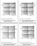

But do you think that the choice of BF998 dual-gate MOSFET N-CH is correct? Can u please verify it for me?
I am skeptical b/c in the data-sheet the graph seems like below (if this way is wrong then please tell me how am i gonna check the cut-off frequency and maximum frequency for a particular part):
Untitled.jpg

- - - Updated - - -

Also Sir if i am right i think the gain control is made through the Voltage at G2 because it determines the thickness of the channel. Can u please provide me the formula or the way how to determine the gain of it?
 

The BF998 is a good choice. It has low noise figure, high top frequency and importantly, protected gates. It should work well as your preamplifier. I use a similar type in microwave amplifiers at 1.5GHz and have no problems. The 'cut-off' frequency is many times higher than you need but that isn't a problem, they work at all lower frequencies as well, it is just maximum as their performance starts to fail. Just be careful with construction, try to keep the components on the G1 side of the amplifier isolated from the output side so you don't get feedback problems. Remember that these devices are capable of considerable gain at much higher frequencies than 27MHz so it is possible for them to go unstable at VHF or UHF without it being immediately obvious. If possible, use a metal can or a shield around the tuned circuits so their magnetic fields can't interact with each other. (hint: Old AM/FM radio usually have several small screened tuning coils and IF transformers with a plastic core you can salvage and rewind)

Varying G2 does indeed control the gain, it isn't a duplicate of G1 though, you can think of it more like two normal JFETS in series, one above the other. I do not have all the formulae at hand but it should be easy to find on the net. Other factors, in particular the tuning coil construction and antenna coupling will have far more influence on the gain than the gate voltages. It is still useful to have a way to turn the gain down though!

Brian.
 
  • Like
Reactions: RMMK

    RMMK

    Points: 2
    Helpful Answer Positive Rating
Status
Not open for further replies.

Part and Inventory Search

Welcome to EDABoard.com

Sponsor

Back
Top