Windmiller
Member level 4

wp100!
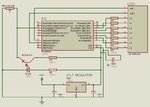
Here's my current code for the PIC16F628A..
It seems to work fine when I was testing it on the 16F.
Regards
/ Morgan
Here's my current code for the PIC16F628A..
Code:
	LIST     p=16f628A

	errorlevel 	-302		; ???

	__CONFIG  	_INTRC_OSC_NOCLKOUT & _MCLRE_ON & _LVP_OFF & _WDT_OFF &	_PWRTE_ON & _BODEN_ON

	ORG     	0x00
	GOTO		INIT

	ORG		0x04		; Interrupt vector
	BCF    		INTCON, INTF    ; Yes, clear interrupt flag
	BCF    		INTCON, GIE    	;
	CALL		IntRupt		; Interrupt routine
	RETFIE

INIT:
Counter 	EQU 0x20	; Delay counter
SaveW		EQU 0x40	; To save W register
DHexVal		EQU 0x28	; Hex value to display
Tens		EQU 0x41	; Dec value to display LCD
Ones		EQU 0x42	; Dec value to display LCD
count1		EQU 0x34	; used in delay routine
counta 		EQU 0x35	; used in delay routine
countb		EQU 0x36	; used in delay routine
Disp10		EQU 0x30	; Displ 1:0
Disp11		EQU 0x31	; Displ 1:1

	BANKSEL 	TRISA
  	MOVLW    	b'00000000'	; Set 0 to input
	MOVWF		TRISA
	BANKSEL 	0x5       	;
  	CLRF    	0x5		; Set All B pins to 0
	BANKSEL 	TRISB
        MOVLW    	b'00000001'	; Set 0 to input
	MOVWF		TRISB
	BANKSEL 	0x6       	;
  	CLRF    	0x6		; Set All B pins to 0

	movlw		0x07		; Turn comparators off and enable
	movwf		0x1f		; pins for I/O functions

       	MOVLW   	b'00110000'	; xx------ unimplemented
					; --11---- prescaler 1:8
					; ----0--- Timer1 osc = off
					; -----x-- ignored when Timer1 osc = off
					; ------0- Clock source = internal (Fosc/4)
					; -------0 Stop timer1

	MOVWF   	0x10		; Set timer

	BSF    		OPTION_REG, INTEDG	; interrupt on positive
     	BCF    		INTCON, INTF    	; clear interrupt flag
     	BSF    		INTCON, INTE    	; mask for external interrupts
     	BSF    		INTCON, GIE     	; enable interrupts

					; 1 Sec delay routine using Timer1
					; With current Timer1 setting (Prescaler 1:8, Reload 3036)
					; a timer overflow happen each 500mSec, so we just
					; repeat it twice
	MOVLW   	.8    		;
    	MOVWF   	Counter		; Counter = 4
	CALL		InitTmr1	; Init timer1

START:  				; Main loop
     	CALL    	CheckTmr1	; Check if tmr1 is done
	movwf		0x22		; Move returnvalue to register
	btfsc		0x22,0		; Is it 0, jump next line.
	CALL		CheckCounter	; Is it 1, Check counter.
	CALL		DispLCD		; Display values on LCDs
	goto 		START

CheckTmr1
      	BTFSS   	PIR1, TMR1IF    ; Timer1 Overflow?
     	RETLW 		0x0          	; Still going, return 0
   	RETLW          	0x1    		; Time's up!

CheckCounter:
	DECFSZ		Counter, F	; Decrease CounterA * 500ms
	GOTO		Jump1		; If not zero Jump1
	GOTO		Jump2		; If zero Jump2
Jump1:	CALL		InitTmr1	; Restart timer
	RETURN				; Return
Jump2:	MOVLW   	.8   		; Reset Counter = 4
    	MOVWF   	Counter		; Counter = 2
	CALL		TimesUp		; Do the thingy
	CALL		InitTmr1	; Restart timer
	RETURN				; Return

DispLCD
					; Display part 0/1 on displ 1
	MOVF		Ones, W		; Put Ones into W
	CALL		LCD10		; Translate W into display10
	MOVWF		Disp10		; Save
	MOVF		Tens, W
	CALL		LCD20
	IORWF		Disp10, W	; Add together

	BCF		PORTA, 0
	BSF		PORTA, 1	; Turn on part 0 for disp 1,2
	MOVWF		PORTB		; Display part 0 on disp 1,2

	MOVF		Ones, W		; Put Ones into W
	CALL		LCD11		; Translate W into display11
	MOVWF		Disp11		; Save
	MOVF		Tens, W
	CALL		LCD21
	IORWF		Disp11, W	; Add together

	BCF		PORTA, 1
	BSF		PORTA, 0	; Turn on part 1 for disp 1,2
	MOVWF		PORTB		; Display part 1 on disp 1,2

	RETURN				; Done

LCD10
	ADDWF		0x2, F
	RETLW 		b'00010110' 	; 0:0
	RETLW 		b'00001100' 	; 1:0
	RETLW 		b'00011100' 	; 2:0
	RETLW 		b'00001100' 	; 3:0
	RETLW 		b'00001010' 	; 4:0
	RETLW 		b'00001110' 	; 5:0
	RETLW 		b'00011110' 	; 6:0
	RETLW 		b'00000000' 	; 7:0
	RETLW 		b'00011110' 	; 8:0
	RETLW 		b'00001010' 	; 9:0

LCD11
	ADDWF		0x2, F
	RETLW 		b'00001110' 	; 0:1
	RETLW 		b'00000000' 	; 1:1
	RETLW 		b'00001010' 	; 2:1
	RETLW 		b'00001110' 	; 3:1
	RETLW 		b'00001100' 	; 4:1
	RETLW 		b'00000110' 	; 5:1
	RETLW 		b'00000110' 	; 6:1
	RETLW 		b'00001110' 	; 7:1
	RETLW 		b'00001110' 	; 8:1
	RETLW 		b'00001110' 	; 9:1

LCD20
	ADDWF		0x2, F
	RETLW 		b'11100000' 	; 0:0
	RETLW 		b'01100000' 	; 1:0
	RETLW 		b'11000000' 	; 2:0
	RETLW 		b'11100000' 	; 3:0
	RETLW 		b'01100000' 	; 4:0
	RETLW 		b'10100000' 	; 5:0
	RETLW 		b'10100000' 	; 6:0
	RETLW 		b'11100000' 	; 7:0
	RETLW 		b'11100000' 	; 8:0
	RETLW 		b'11100000' 	; 9:0

LCD21
	ADDWF		0x2, F
	RETLW 		b'10110000' 	; 0:1
	RETLW 		b'00000000' 	; 1:1
	RETLW 		b'01110000' 	; 2:1
	RETLW 		b'01100000' 	; 3:1
	RETLW 		b'11000000' 	; 4:1
	RETLW 		b'11100000' 	; 5:1
	RETLW 		b'11110000' 	; 6:1
	RETLW 		b'00000000' 	; 7:1
	RETLW 		b'11110000' 	; 8:1
	RETLW 		b'11000000' 	; 9:1

TimesUp
	MOVF		0x21, W		; RPM
	MOVWF		DHexVal		; Display value
	CLRF		0x21		; Clear out, start over
	CALL		HexToDec	; Convert Hex to Dec
	RETURN

HexToDec				; Convert Hex to dec
	CLRF		Ones
	CLRF		Tens
	movf		DHexVal, W	; Get hex value to convert
	movwf		Ones
repeat:	movlw   	.10
	subwf		Ones, W
	btfss		STATUS, C
	RETURN				; Done converting
	movwf		Ones
	incf		Tens, f
	goto 		repeat

InitTmr1
	BCF     	T1CON, TMR1ON   ; Stop Timer1
     	BCF     	PIR1, TMR1IF    ; Clear Timer1 overflow flag
       	MOVLW   	b'11011100' 	; Load
    	MOVWF  		TMR1L       	; Timer1
  	MOVLW   	b'00001011'	; with
        MOVWF   	TMR1H       	; Reload Value
     	BSF     	T1CON, TMR1ON   ; Start Timer1
	RETURN

IntRupt
	MOVWF		SaveW		; Save what's in W
	INCF		0x21, f		; Increase RPM counter
	MOVF		SaveW, W	; Restore W
	RETURN				; And return

	End
It seems to work fine when I was testing it on the 16F.
Regards
/ Morgan


")