Continue to Site

Welcome to EDAboard.com

Welcome to our site! EDAboard.com is an international Electronics Discussion Forum focused on EDA software, circuits, schematics, books, theory, papers, asic, pld, 8051, DSP, Network, RF, Analog Design, PCB, Service Manuals... and a whole lot more! To participate you need to register. Registration is free. Click here to register now.

Why would MOSFETs heat up in an inverter while charging with the same inverter

Status
Not open for further replies.

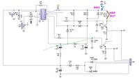
All FETs are shown connected wrong way. This must only be in schematic drawn otherwise inverter won't be working. Similarly R1 And R2 be 100 ohm like other gate resistors.
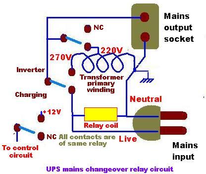
When mains is restored, a relay connects mains input to mains output after disconnecting inverter output and also disconnects DC from control circuit.
4788792600_1351453341.jpg
 
Last edited:

    V

    Points: 2
    Helpful Answer Positive Rating
It is not advisable to make 3.5Kva inverter using 24vDC , you are dealing with almost 146 A, which is too high. Battery voltage should be at least 60Vdc.

Because you are using a transformer of 146A capacity if the charging is not controlled using some circuit it will surely heat up. please post the charging circuit.
regards ani
do you mean the charge controler circuit
because there no other circuit apart from those ones you up there

- - - Updated - - -

Dear sam1145,

I have also faced this kind of situation.In inverter mode it was working fine but in charging mode both channels start heating

(sometimes it burnt).I have checked sg3524 osc. was off but there was about 0.3v present at the gate of FET's. Changing

the driver transistor solved my problem (it was a leakage current ). In your case replacing Q13 & Q14 may solve the problem.

Thanks
replace it with what other value?
 

Try to use "totem pole" driver,gates of fets become 0 volt during charge.
 

@ALERTLINKS thats very correct the circuit shudnt work in the first place: i'll advice he run a circuit analysis if he hasnt so dat he can come up with exactly wot he has there else it will be dificult to help.
 

do you mean the charge controler circuit
because there no other circuit apart from those ones you up there
You can test weather a charging circuit is necessary or not by the following experiment.
1 switch off the inverter
2 remove the mains and battery
3 disconnent the Cn4 connector
4 short gate to sorce of power Mosfets
5 connect battery
6 connect mains
Now measure the charging current with a clipon ammeter and post , If the mosfets still heats up you will require some circuit to controll charging
 

Dear Sam,

I have simply used BC547 to sort out my problem.you can confirm whether our problem is same or not just remove Q13 & Q14 and start charging.Now check the heat sinks, "if it

still heating you need to revise the transformer & MOSFET Bank circuit".

Thanks
 

Check the outputs of the driver stage (to MOSFET gate) to ensure that no gate drive signals are generated.
It is best to observe the signal on an oscilloscope. You can also use a voltmeter to see if the outputs show a steady 0V.
thanks Tahmid,i used the multimeter and its reading -0.205v and when reverse the props its +0.205v

- - - Updated - - -


All FETs are shown connected wrong way. This must only be in schematic drawn otherwise inverter won't be working. Similarly R1 And R2 be 100 ohm like other gate resistors.

When mains is restored, a relay connects mains input to mains output after disconnecting inverter output and also disconnects DC from control circuit.
4788792600_1351453341.jpg
the relay is it VAC powered?
 

One more thing is that the outputs of the SG3524 should be pulled down. Either connect pull-down resistors from pins 11 and 14 to ground or connect pull-down resistors from bases of Q13 and Q14 to ground.
like what value of resistor ?

- - - Updated - - -

can someone post the a detailed transformer winding formula for 3.5kva/24vdc inverter
 

@ALERTLINKS the grounding in the above switching diagram,is it just to the chases[the inverter case]
 

It is 14pins 220Vac relay commonly used in UPSs. It contains four switches. As three of them are used, the fourth is paralled to increase current handling. Grounding is somtimes shown for neutral wire. It is not connected to ground or chassis.It is only indicative of neutral wire. If you need grounding, it is connected to third prong which goes to earth connection and is not shown in diagram.
 

can someone post the a detailed transformer winding formula for 3.5kva/24vdc inverter
3.5Kva*746=2611 watts.
Small transformer,s efficiency 90%.
So,we need 2611+261=2872 watts transformer.
I am adding 10% losses(261w) in total wattage.
We need 10 square inch bobbin size,may be 2.5*4 or 2*5.
2.5 inch core have much stack height,and is suitable for your transformer.
Now we need to select wire gauge.
2611\24=load on battery and secondary winding,108.7Amp.
For almost 110 Amp,we should select SWG,8 bifilar ( 2 wires of swg,8 parallel).
Now primary winding wire should be,
2611/220=11.8 amp.
For primary swg 15 is suitable in 2.5*4 bobbin.
17.5+17.5 turns are for secondary.
And 176,192,200 turns are for primary.
200 turns for 250v.
192 turns for 240v.
176 turns for 220v(charging loop).
I suggest you reduce battery size and make with 48v dc.
 
Last edited:

3.5Kva*746=2611 watts.
Small transformer,s efficiency 90%.
So,we need 2611+211=2872 watts transformer.
I am adding 10% losses(211w) in total wattage.
We need 10 square inch bobbin size,may be 2.5*4 or 2*5.
2.5 inch core have much stack height,and is suitable for your transformer.
Now we need to select wire gauge.
2611\24=load on battery and secondary winding,108.7Amp.
For almost 110 Amp,we should select SWG,8 bifilar ( 2 wires of swg,8 parallel).
Now primary winding wire should be,
2611/220=11.8 amp.
For primary swg 15 is suitable in 2.5*4 bobbin.
17.5+17.5 turns are for secondary.
And 176,192,200 turns are for primary.
200 turns for 250v.
192 turns for 240v.
176 turns for 220v(charging loop).
I suggest you reduce battery size and make with 48v dc.
@pnjbtr: haw did you get 746 and 211 up there?
 

@pnjbtr: how did you get 746 and 211 up there?
Sorry it is calculation mistake original value is 261.
261w is 10% losses in iron and copper wire
When we calculate power units.
We use terms of watts,Kw.
Va and Kva.
In Ac power calculation, Va is less then watts.
And 1kva =746 watts.
For detail see https://www.rapidtables.com/electric/electric_power.htm
 

It is going to be very tough to handle SWG 8 bifilar binding, so I also suggest to increase no. of batteries .If You use 48v then SWG 10 can be used & in case of 60v SWG 12 will be enough.
However, for 3.5KVA/24V I will use
Bobbin------2.5*4
Primary------18/18--------8SWG
Secondary---125+85------15/16 SWG
 

can anyone post the set of codes and hex file if possible for 8051 micro controller sine wave oscillation of an inverter
 

Status
Not open for further replies.

Similar threads

Part and Inventory Search

Welcome to EDABoard.com

Sponsor

Back
Top