Continue to Site

Welcome to EDAboard.com

Welcome to our site! EDAboard.com is an international Electronics Discussion Forum focused on EDA software, circuits, schematics, books, theory, papers, asic, pld, 8051, DSP, Network, RF, Analog Design, PCB, Service Manuals... and a whole lot more! To participate you need to register. Registration is free. Click here to register now.

Why the battery voltage is not rising up from 13.2 volts to 14 volts or to even 14.4

Status
Not open for further replies.
The current measurement clearly shows very normal operation... If the float voltage of battery is also 13.2V then no need to change the charger settings at all.. That is good for battery life as well....
 

Kindly provide me the circuitry schematic and the ratings of components to build a DIY 10 Amps battery charger.

would that 10Amp battery charger be suitable for 90AH , 12 V battery for slow charging to not to damage the battery cells and plates ?
 

Optimal charging of LEAD ACID battery will pump in 1/10 In Amps of the rated AH to the battery during bulk charge stage. so a using current limited 10Amps charger for 90AH battery will be very slow. to avoid damaging the cells, devise a way to lower the bulk charging voltage to a float charge voltage. The challenge with lead acid batteries is the floating voltage, if very high than recommended by manufacturer, the cells will eventually dry out(gassing effect), rendering the battery useless. Also consider pulse chargers as an option.
 

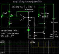
For my solar panel and battery bank setup, I constructed the simple charge controller shown below.

It charges at full panel output, until the battery rises to 14.4 V.
Then it shuts off.
After a few minutes the battery settles to a lower volt level.
When it drops to 13.8V, charging resumes.
This continues the remainder of the day.

Hysteresis is the principle by which the op amp turns charging on and off.
It is a simple way to provide full charge to the battery (sunlight permitting), and yet avoid overcharging.


- - - Updated - - -

My simulation uses a transistor because it make it easier to manage current flow (whereas mosfets do not always turn on sufficiently in Falstad's simulator).

My real circuit used a mosfet, which does turn on sufficiently in response to the volt level at the bias terminal.
 

Status
Not open for further replies.

Part and Inventory Search

Welcome to EDABoard.com

Sponsor

Back
Top