Continue to Site

Welcome to EDAboard.com

Welcome to our site! EDAboard.com is an international Electronics Discussion Forum focused on EDA software, circuits, schematics, books, theory, papers, asic, pld, 8051, DSP, Network, RF, Analog Design, PCB, Service Manuals... and a whole lot more! To participate you need to register. Registration is free. Click here to register now.

[SOLVED] Why do we use zener diode as Voltage reference in Comparartors

Status
Not open for further replies.
In an earlier post you said that you are using a 6V battery as the op-amp's supply. The supply has to be a higher than the maximum voltage you want to monitor.
To monitor for 6.9V, you need a supply which is a couple of volts higher than that, say 9.

Can you confirm that you can do that?
 

You can monitor a supply higher than your opamp supply - you simply scale the voltage with resistors to bring it in range of the opamp (or microcontroller). This is quite common for battery monitoring with a microcontroller where the supply might be 3.3V and the battery 6V, and you feed a scaled version of the battery to a microcontroller ADC pin.

Keith
 

in my opinion,in order to achieve your goal,you can use a zener diode as Voltage reference,but in other system such as A/D or D/A convert it may dos not work,these systems require high-precision.
 

You can monitor a supply higher than your opamp supply - you simply scale the voltage with resistors to bring it in range of the opamp (or microcontroller). This is quite common for battery monitoring with a microcontroller where the supply might be 3.3V and the battery 6V, and you feed a scaled version of the battery to a microcontroller ADC pin.

Keith

Thanks keith1200rs. I have used Potentiometer connected from Battery to Non-Inverting Pin of LM358. It shows GREEN LED when the battery voltage goes up above 3.3v (that I set using 3.3v zener- resistor combination) of reference voltage of Inverting Pin. As you suggested Should I use voltage divider to set the 6.9v as High Voltage (of course for 5.5v Low voltage also) instead of Potentiometer? That is, I have to use voltage divider to supply 3.3v to Non-Inverting Pin of LM358 to compare with Inverting Pin reference voltage (3.3v) when the battery reaches 6.9v? Is this correct? This is also applied to Low voltage? For example pl see the picture:

View attachment edaboard_VoltDivider.bmp
 

Thanks to Syncopator and zhangsenele for your valuable suggestions.

thanks
pmk
 

In an earlier post you said that you are using a 6V battery as the op-amp's supply. The supply has to be a higher than the maximum voltage you want to monitor.
To monitor for 6.9V, you need a supply which is a couple of volts higher than that, say 9.

Can you confirm that you can do that?

Sorry, I was half asleep when I wrote that. Please disregard it.

A new post follows.
 

Its Ok Syncopator. With the help of you and all, I am nearly in the final stage of the project. Thanks a lot.

thanks
pmk
 

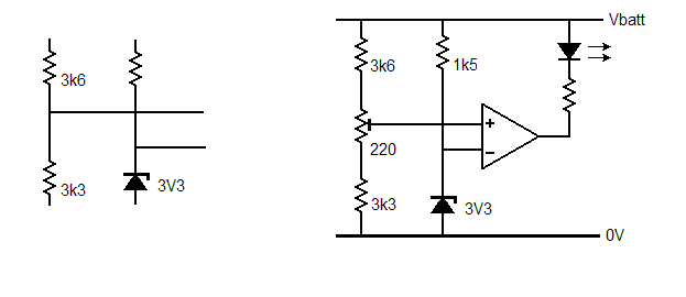
Since you are applying, say, 3.3V as reference, you need the amplifier to switch its output from one state to the other when the other input is just above or just below 3.3V.

You need a voltage divider on the other input which gives, at its junction, 3.3V when the supply is 6.9.

So, across the upper R of the divider there will be 3.6V. Just use resistors in the same ratio, as shown in the left hand diagram below.

If the voltage at which the amplifier switches is critical, insert a low value potentiometer as shown in the right hand diagram. Then, ideally with a variable power supply, set the supply to 6.9V and adjust the potentiometer.

battmon.gif
 

Attachments

  • battmon.gif
    battmon.gif
    4.5 KB · Views: 117
Thanks Syncopator for the circuit provided. Now, Hope the problem has been solved. I think, I can finish my project now. Once again thanks a lot. Bye
 

Status
Not open for further replies.

Similar threads

Part and Inventory Search

Welcome to EDABoard.com

Sponsor

Back
Top