Continue to Site

Welcome to EDAboard.com

Welcome to our site! EDAboard.com is an international Electronics Discussion Forum focused on EDA software, circuits, schematics, books, theory, papers, asic, pld, 8051, DSP, Network, RF, Analog Design, PCB, Service Manuals... and a whole lot more! To participate you need to register. Registration is free. Click here to register now.

Which device can I use ?

Status
Not open for further replies.
I tried SR latch which has only Q outputs. I used a NOT gate to get both Q and !Q outputs but one of the LEDs will be ON initially even if no button is pressed. It will be helpful if a example circuit is provided.


Edit:

I made this circuit. Is this right ? It works as expected.

I want to know why channel (ch) 1 and ch 2 has two Set (S) inputs ?
 

Attachments

  • togled.png
    togled.png
    17.4 KB · Views: 99
Last edited:

I made this circuit. Is this right ? It works as expected.

Yes, but it isn't better in any regard than the previously suggested two NAND circuit. I believe that the SR latch is introduced as first memory circuit in most digital logic textbooks.
 
I tried SR latch which has only Q outputs. I used a NOT gate to get both Q and !Q outputs but one of the LEDs will be ON initially even if no button is pressed. It will be helpful if a example circuit is provided.

The only time no buttons have been pushed is at power on. If you want a auto reset on power on, you can add a flipflop and gate the two outputs from your SR flipflop. 74hc74 has 2 SR flipflops with both Q and /Q outputs, and you can combine those to with some logic to make your circuit.
 
I tried SR latch which has only Q outputs. I used a NOT gate to get both Q and !Q outputs but one of the LEDs will be ON initially even if no button is pressed.
Sounds like a "hidden" specification that hasn't mentioned before post #22. If you want a third state "both LEDs off", you'll need at least two storage elements, a completely different circuit.

I think you should clarify your specification. Preferably sketch a state diagram.
 
I have already explained. It uses two buttons as shown in post #22. It is the actual circuit. One button is used to trigger an SCR gate and another to turn of SCR. There is a transistor in series with SCR. When transistors base is connected to GND (NPN) the SCR turns off. I just need to show the two states. Only one signal the one firing the SCR and another grounding the base of transistor can go low at a time. Both cannot go low at the same time but both can be high all the time when buttons are not pressed. Initially the SCR is off and I want to show it with red led of Bi-Color led and when SCR turns ON I want to show it as green led of Bi-Color LED. That is all the circuit.

And Ofcourse there is a NOT gate 74HC04 between one button line and SCR gate. When button line goes low then NOT gate and hence gate goest high and SCR conducts.

- - - Updated - - -

I tried method in post #24 by Gorgon using 74HC74 but it works without SCR circuit but with SCR circuit it doesn't work. I am posting the circuit. This is a rough circuit which I need. Proper resistors are not added in HeX Inverter circuit. Power supply is 12V as it has to drive a 12V relay. The buttons are actually float switches. The relay drives a Pump.


106900d1404201790-scrcircuit.png
 

Attachments

  • scrcircuit.png
    scrcircuit.png
    20.3 KB · Views: 104

If you add a capacitor in parallel with the 'OFF' button, there should be a delay added to reset the flipflop when power comes on, and light the red LED. The size of the capacitor is epending on the pullup resistor for the button.

- - - Updated - - -

A silly question. Why do you need the SCR ar all, why not use the flipflip to control the transistor and use that as a combined display and relay control?
 
with SCR circuit it doesn't work.
Yes, because Q2 base connection is pulling the off-button voltage down to about 1.5 V when the thyristor is latched.
 

Fixed the circuit. Now it works fine. I have to use SCR. It simplifies the design and keeps the circuit small. C106M1 (C106D) SCRs are cheap here. I need two such circuits as there will be 2 Bi-Color LEDs. One 74HC74 will do the work. In the final Circuit. The Hex Inverter will be replaced by a BC547 or even BC847 (SMD) transistor. Proteus 8.1 SP1 file attached.

106903d1404204074-scrpumpcontrol.png
 

Attachments

  • pumpcontrol.rar
    18.2 KB · Views: 100
  • scrpumpcontrol.png
    scrpumpcontrol.png
    21.6 KB · Views: 109

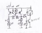
How about an all transistor device?
 

Attachments

  • flipflopt.jpg
    flipflopt.jpg
    216.7 KB · Views: 88

What is the value of C across switch 100 nF ? 10uF ?


I need another circuit in which the button circuit will be same but both LEDs (BI-Color) should be off initially and depending upon which button makes signal low corresponding LED color has to latch and remain in that state even if that signal goes low repeatedly. The LED color changes when another signal goes low. The only difference compared to previous circuit is I need both LEDs (colors) to be initially off.
 

Between 100nF and 1uF should be ok. It depends on how fast the 12V is coming on. If the 12V is ramped up you need to use a bigger capacitor.

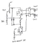
Regarding your last question, here is a logic approach:
 

Attachments

  • flipflop1.jpg
    flipflop1.jpg
    198.6 KB · Views: 85

What device LEDs are connected to ? D Flip Flop ?
 

You can use the 74hc74 for the flipflops, and the gates are NOR-gates.
 

Ok. Thank you. I will try and update.

Edit: Gorgon, its not working the second circuit. I used 1N4148 for the diodes and 100nF for Capacitor in RESET circuit.

Edit 2: Sorry, there was a mistake in my circuit. It works. :grin:

- - - Updated - - -

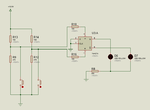
How can I modify this circuit such that the outputs of SR Flip Flop in addition to displaying the status through LEDs should also enable or disable or enable (toggle) 12V and 5V power to a circuit using transistors ?
 

Attachments

  • circuit b.png
    circuit b.png
    11.8 KB · Views: 81
Last edited:

Status
Not open for further replies.

Part and Inventory Search

Welcome to EDABoard.com

Sponsor

Back
Top