Easy peasy
Advanced Member level 6
A diac is in fact a triac, with internal resistors such that it breaks down to a volt or so ( as long as there is sufficient current to keep it on ) once the off state firing voltage is reached
Follow along with the video below to see how to install our site as a web app on your home screen.
Note: This feature may not be available in some browsers.
Hi,
When the switch is open, then node may be seen as "floating". Floating means "undefined" .... anything can happen.
That's why I wrote "2) the switch is of no help. It makes things more difficult.".
An "open switch" is not the same as "Zero volts".
Klaus
Please tell which of Brian´s posts are you talking about. Can´t remember he talked about oscillation. But maybe...My understanding to what Brain told me, is that when the capacitor is charged up with the amount of voltage that should trigger the diac, it discharges and the diac conduct. As the capacitor is charging up again the diac should go back to off state. But that didn't happen, so anyway I don't know how to do it.
Hi,
Please tell which of Brian´s posts are you talking about. Can´t remember he talked about oscillation. But maybe...
Klaus
Form the previous discussion you already should know that 1) not useful ... at least problematicI have now different versions of triggering in my mind:
1. Ordinary RC circuit
2. RC with DAIC
3. RC with UJT
4. Zero crossing detection connected to a UJT
Hi,
Form the previous discussion you already should know that 1) not useful ... at least problematic
2) is good for analog phase angle control
4) is good for digital phase angle control
I recommend to go on with 2).
* fixed R, fixed C as timing control
* diac to get proper gate trigger
* measure the gate current with a scope
Don't longer use try and error method.
Calculate the values.
* R to get less than 250mW of power dissipation.
* C to get a useful phase angle
* measure the gate current with a scope
* then compare the scope results with the SCR datasheet limits and decide whether or not you need a current limiting gate resistor.
Show us what you do ... step by step.
Racing Klaus.....
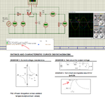
This is a DB3 Diac, 100K resistor and 100nF capacitor:
View attachment 158594
and this is what I see on the scope:
View attachment 158595
Brian.
I think we are going nowhere fast.
I can't confirm what your simulator tells you because I don't use Windows and as far as I know Proteus doesn't run in Linux. However, it seems to behave strangely and maybe the Diac model is incorrect. The picture in post #88 clearly shows what happens in real life and apart from using fixed components and a DC source,
the schematic is essentially the same as in your last simulation. Where the sawtooth waveform suddenly drops is where the Diac conducts, if it had a 20 Ohm resistor in series with it like in your schematic, it would show the pulse as in the data sheet. I'll add a 20 Ohm resistor and show you the result tomorrow (it's too late at night here to start building things!).
Quite confusing statement.But there's a problem in this regard which is that I can't control the amount of voltage that goes to the gate, thus I can't control the amount of current which should be constant during all phase control trigger process.
You use an RC circuit with AC source and wonder about phase shift ... really?Also why the signal on the capacitor and after the diac aren't in phase with source signal ?
* The gate voltage is meaningless (as mentioned in posts before, several times)I just have a question about the best way to measure the gate voltage and thus calculating the gate current.
No. This relationship (0.707) is only true for non distorted, sinusoidal waveforms without DC offset, which the gate current not is.Is it enough to measure the rms voltage drop on R1 and then divide that by 0.7071 to get the peak voltage.
You measured the sum, not the difference. So your result is not correct.But with the scope I'm getting that the voltage difference across R1 is 20V. So which is correct ?
First we focus on "safe triggering an SCR" ... in future we will avoid malfunction. Then the diode may be of help. ...later1. I added a diode to prevent negative voltages across C1 and also since I don't need the negative voltages to have negative triggering pulses which would needed in a TRIAC circuit.
The maximum allowed gate current is far higher than 48mA.2. I've put a series resistor 4.7k as I found it the most appropriate to get maximum current of 48mA at the gate which is the max rated current for this SCR.
No good idea. How often did we mention before that the gate voltage is not much of interest....I wonder why you still insist in talking about gate voltage....I just thought of adding a voltage divider at the gate, is it a good idea ? I can split any incoming voltage the the balance I want.
The 1.5V is not the allowed limit, the 48mA is not the allowed limit, thus the result is wrong. Not only the result is wrong, but also the way you used. With your way you calculate the internal resistance (although the gate has no resistive behaviour) ... but need the value of an external current limiting resistor.According to the datasheet, if the gate voltage is at max which is 1.5V then the resistor that should be used in series with the gate is 33 ohms, so I tested that and I think I understood a little of how to get close to what the datasheet is telling me.
I would be pleased if I could agree...and I think I understood a little of how to get close to what the datasheet is telling me.
Following on from post #91:
View attachment 158619
I actually used 22 Ohms in series with the Diac but that is irrelevant for this argument.
You will notice the same sawtooth waveform, it rises as the capacitor charges through the 100K resistor then the Diac triggers causing the capacitor to discharge through the diac and 22 Ohm resistor. The bottom trace is across the 22 Ohm resistor so it shows a voltage proportional to the Diac current. I am actually running it from 64V DC because thats the maximum my bench supply can manage but it works from anything from around 40V upwards.
Note carefully that the 100K resistor from a 64V supply cannot pass more than 0.64mA yet the current pulses are at least 7V high which across 22 Ohms means the current must be 318mA.
What is happening is the capacitor is providing the diac current, not the 100K although a tiny amount does still come through the 100K as well.
A Diac is bi-directional and symetrical, if you use AC instead of DC it will still work but the pulses will be mirrored when the polarity is reversed.
You would have to take into account the AC frequency and the RC time constant, obviously if the supplied voltage doesn't have time to charge the capacitor before it reverses and discharges it again, the Diac breakdown voltage may not be reached.
It is used commercially as a very low cost oscillator but the frequency depends on the applied voltage (hence capacitor charging time) and the tolerance and stability of components which for high voltages may not be too good. It is used for warning lamp flashers, audible alarms and the likes but is far too unstable for most uses.
Hi,
Issues:
* The gate voltage is meaningless (as mentioned in posts before, several times)
* you can't calculate the gate current from the gate voltage (at least not in a usual way). Gate_voltage is not proportional to gate_current, non ohmic behaviour, nonlinear
* your scope channel C needs to be inverted (also mentioned before) to get the gate current
No. This relationship (0.707) is only true for non distorted, sinusoidal waveforms without DC offset, which the gate current not is.
* The RMS current is not of interest when triggering an SCR, only the peak current. It can be measured with the resustor and differential scope mode, thus we recommended this method. There should be a peak. The peak triggers the SCR. . After the peak there may be any current (as long as it does not destroy the gate): zero, negative, positive, low current, high current ... it simply does not matter.
Before the peak there should be almost zero current .... and is not much of interest
You measured the sum, not the difference. So your result is not correct.
But at least here you are close to a useful value: invert channel C.
First we focus on "safe triggering an SCR" ... in future we will avoid malfunction.
Then the diode may be of help. ...later
The maximum allowed gate current is far higher than 48mA.
No good idea. How often did we mention before that the gate voltage is not much of interest....I wonder why you still insist in talking about gate voltage....
The 1.5V is not the allowed limit, the 48mA is not the allowed limit, thus the result is wrong. Not only the result is wrong, but also the way you used. With your way you calculate the internal resistance (although the gate has no resistive behaviour) ... but need the value of an external current limiting resistor.
I wonder where you have the "48mA" from. When I do a search at the datasheet PDF on "48" there are no hits.
I would be pleased if I could agree...
"48mA" maybe is the "max gate trigger current" ... not the "max gate current" ( which is 8A in my datasheet) .
The trigger current may vary from part to part (like the size of feet with humans) and it may vary with conditions like temperature.
Some may trigger with 30mA, many will trigger with 40mA, most will trigger at 45mA, but all of this type of SCR at all conditions will trigger with 48mA. Means your external trigger circuit needs to deliver at least (minimum!) 48mA of trigger current to safely trigger these SCR in all conditions.
is it specifically for the polarized capacitors or non-polarized capacitors or both types.
A capacitor is a capacitor, electrolytic is just one type of construction. The charge is held across the capacitor, regardless of polarity so it isn't true to say it is only held at the positive end. Whether a capacitor is polarized or not depends on what type it is, generally only electrolytic types are polarized and they tend to be used when higher values are needed. There are 'non-polarized' electrolytics too but they are only used is special applications.
Discharge: Pin 7 is called the discharge. This pin is used to discharge an external capacitor that works in conjunction with a resistor to control the timing interval. In most circuits, pin 7 is connected to the supply voltage through a resistor and to ground through a capacitor.
1. IGTmax is the MAXIMUM current you should ever need to trigger the least sensitive sample of that device, most will trigger at lower currents.
3. Yes, but that is the MAXIMUM rating that must not be exceeded, not the one you design to.
2. Most devices ratings are based on how long the specified parameter can be held before it overheats. You will see the different current ratings relate to different durations. The 160A reference relates to the voltage drop across it at that current and how much heat it would dissipate.
TM8050H-8D3 device is an
800V SCR thyristor suitable for applications where high power switching (IT(RMS) = 80
A) and low power dissipation (VTM = 1.55 V at 160 A) are key features.
4. Yes, but measured under different conditions, the trigger current is somewhat dependent on the other factors.
5. Yes with 12V applied across the device and with a 33 Ohm load resistance.
Each user will design slightly differently and that device could be used for many purposes, the reason they give you such information in the data sheet is so you can see if it is suitable for the purpose you intended. It is a general purpose SCR which means it can be used in many applications, some DC, some AC and for completely different purposes. The manufacturer cant give all figures for all uses so they provide sample figures to demonstrate what it is capable of doing in different situations.