Continue to Site

Welcome to EDAboard.com

Welcome to our site! EDAboard.com is an international Electronics Discussion Forum focused on EDA software, circuits, schematics, books, theory, papers, asic, pld, 8051, DSP, Network, RF, Analog Design, PCB, Service Manuals... and a whole lot more! To participate you need to register. Registration is free. Click here to register now.

[SOLVED] want to build ir receiver of 38khz

Status
Not open for further replies.
The attached circuit is exactly implementing the said second (250 Hz) modulation at the transmitter side and can be expected to work good. But it hasn't much to do with the previously posted circuits in this thread.
 

hiten09 Let me Say Something....

Connect the OUT pin of the TSOP1738 with the micro-controller's interrupt pin...
Okay

So when ever u got an IR Right TSOP wil produce fluctuations...
and that will interrupt ur controller...
When ur Controller gets interrupted... Just Blink the LED by using another pin of the controller...

Try to do this .. Hope this will work..

sorry for late reply i tried that circuit given by arunsharma0731 . but the problem is the led glows all the time and when the ir beam is present it blinks but doesnt switches to off state, so i can observe that it is receiving the ir but how microcontroller would read this as it is fluctuating. as said in above post by varunme . is there any way to do this pls share it

According to ur post...
When IR is there ur LED Blinks..
and when IR is Not there ut LED glows continuously ...

This means that ur transmitter is working properly....

What else u want to know...

Just try what i had said above...

Hope it helps u...
 

so , for just one digital pulse, that circuit is not usable ....
 

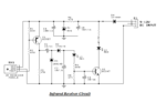
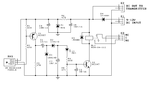
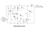
yaa firstly i asked here if anyone have any workable circuit but i didnt got any, then i got this cicuit from one of my friend but while using this i made the transmitter but having problem in receiver, finding again any new circuit will not make any result thats why i am asking problem with this circuit only ir receiver circuit.pngoriginal.png now the problem is i replaced the relay in original circuit by a resistot and a led but its not working can you guide me what to do
 

arunsharma0731
Connect the OUT pin of the TSOP1738 with the micro-controller's interrupt pin...
Okay

So when ever u got an IR Right TSOP wil produce fluctuations...
and that will interrupt ur controller...
When ur Controller gets interrupted... Just Blink the LED by using another pin of the controller...

Try to do this .. Hope this will work..
ok i will try this and will share the result with you
 

The receiver circuits from post #45 are intended to work with a modulated 38 kHz carrier as generated by the transmitter from post #39. They don't work with 38 kHz CW. If the transmitter/receiver combination also doesn't work, there's most likely something wrong with the assembly, we can't easily debug it from a distance. You need to check the signal at individual circuit nodes to understand why it's not working.
 

but this is transmitter, i am asking about receiver

Hi,

I guess you already know the low cost standard IR receiver 3-pin IC. It is used globally mainly in satellite receivers and TVs.

In my IR projects, I built the IR transmitters as you did (though using also an MCU to send data). But I got ready IR receivers to save space, time and money and to get good sensitivity. Just in case you didn't work with such IC yet (it looks like the BD135 transistor with an IR lens instead of the hole), its 3 pins are:

Vcc, usually it works on 5V (I used to add 220 Ohm resistor in series and a 220uF capacitor between this pin and ground).

Data, it may need a pull-up resistor (I choose its value as 4K7 between this pin and the IC Vcc pin).
Added: This pin can then be connected directly to an MCU interrupt pin to read the time intervals between pulses... etc.

Ground.


Of course, you can always build the IR receiver by using an IR photodiode, amplifier, bandpass filter and detector.

Kerim

Edited:
Very Sorry, I just noticed that I missed reading all posts on pages 2 and 3 before writing this reply :oops:
 
Last edited:

sorry for late reply, i tried 2 circuits but one didnt worked and another is having the same relay used in it so i modified my old circuit but its having a litle problem.
firstly have a look at this circuit
ir receiver circuit.png

now the problem is both these leds blinks when i provide the supply to this ckt, i senses the ir the only problem is it blinks in absense of ir after a fix interval of some microseconds. pls share your view how to make it stable

and pls also tell about using an digital ic for converting the output of this ckt into digital format so that i could connect it to microcontroller
 

I got it working without any additional circuitry of using an oscillator
 

dude can you upload the schematic of your receiver
 

Hi Hiten09,

Sorry, it is not clear yet what exactly you are looking for.

If you send a continuous 38KHz, you get at pin1 of RX1 a continuous low voltage (RX1 output, when on, sinks current).
When 38KHz signal is off, you likely get at pin1 a high voltage (by using a pull up resistor as R2 if connected to 5V) and random short pulses (to ground) because of noise/interference.

The node of this pin1 (connected to the MCU Vcc via a pull-up resistor, about 4K7) could be connected to an MCU pin (better if it is an interrupt pin). The role of the MCU would be then to measure the time between two falling edges for example (as it is the case for my Atmel C51 MCUs) and decide when it is valid. Actually more than one time interval are measured to be sure the received pattern is valid. The pattern of the IR pulses carried on the 38KHz could be very simple (same period) or complex like a series of 0 and 1 bits (0 could be a short period interval and 1 a relatively long one, say twice). Also a starting long pulse could be added prior of a data packet that is formed by 32 bits for example. This long starting pulse could be 10ms or more and it has two functions; it signals the starting of a new code and it prepares the IR receiver to detect properly the coming short pulses after it (without noise). Usually, the shortest interval is 1ms (if less the detection distance decreases).

Hope this helps.

Kerim
 
  • Like
Reactions: ggmssr

    ggmssr

    Points: 2
    Helpful Answer Positive Rating
Status
Not open for further replies.

Similar threads

Part and Inventory Search

Welcome to EDABoard.com

Sponsor

Back
Top