Continue to Site

Welcome to EDAboard.com

Welcome to our site! EDAboard.com is an international Electronics Discussion Forum focused on EDA software, circuits, schematics, books, theory, papers, asic, pld, 8051, DSP, Network, RF, Analog Design, PCB, Service Manuals... and a whole lot more! To participate you need to register. Registration is free. Click here to register now.

walk-through metal detector

Status
Not open for further replies.
Hi,

Would you be kind to explain me the following point:

If my design works on DC voltage, how it will pick the mains hum ( at 50 Hz)?

Thanks & Regards.

- - - Updated - - -

Hi,

Would you be kind to explain me the following point:

If my design works on DC voltage, how it will pick the mains hum ( at 50 Hz)?

Thanks & Regards.

- - - Updated - - -

Hi,

Would you be kind to tell me the following point:

1. What should be the no. of turns of the transmit coil and the receiver coil for a walk-through metal detector?
2. What should be its shape, Elliptical or Rectangular for a walk-through metal detector?

Thanks.

- - - Updated - - -

Hi,

Would you be kind to tell me the following point:

1. What should be the no. of turns of the transmit coil and the receiver coil for a walk-through metal detector?
2. What should be its shape, Elliptical or Rectangular for a walk-through metal detector?

Thanks.

- - - Updated - - -

Hi,

Thanks for your valuable feedback.

I have attached the schematic of the Transmitter circuit for a walk-through metal detector. I am using Wien Bridge oscillator for generating 18 KHz frequency and transmitting it through a transmitter coil into the air.
Would you be kind to tell me the following point:

1. What would be the optimum no. of turns of the transmitter coil for a walk-through metal detector for 18 KHz signal?
2 Should it be an elliptical or rectangular in shape?

Thanks.
 

Attachments

  • transmit_ckt.png
    transmit_ckt.png
    32.4 KB · Views: 103

Hi,

Would you be kind to explain me the following point:

If my design works on DC voltage, how it will pick the mains hum ( at 50 Hz)?

Thanks & Regards.

Based on the Receiver Circuit you showed Previously, It is NOT just a DC Voltage.
Your receive coil is coupled to the amp via a .001 capacitor.
Any 60 hz can also pass through.

And I Really Doubt this design will detect much of anything.
 

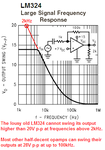
Guess what? Your lousy old LM324 opamp works poorly above 2kHz, your frequency is 18kHz.

Also, the output current from the opamp is so low that it cannot drive the very low reactance of the output coil.
 

The LM324 only needs a gain of 3 to oscillate so it might still produce something at 18KHz, I'm not suggesting it would be a sine wave or anything like one! There is no chance of it producing anything like the current needed to create such a big field and I have already advised a big amplifier would be needed. I have no experience with this kind of metal detctor but intuitively, I would say a higher frequency should be used, maybe 100KHz - 200KHz for better sensitivity.

The 50Hz/60Hz problem is due to the high background electromagnetic field strength found almost everywhere. It is created by anything with a mains transformer in it and even the power wiring in the room or nearby. It is possible to 'notch filter' it out otherwise it may be the dominant signal you see.

I still think you are wrong to use the transformer/eddy current method for detection. Using the inductance shift of the coil in the presence of metals would be a better method and easier to build.

Brian.
 

The slew rate of a lousy old M324 is so slow that at only 2kHz when the output reaches a peak of only 10V then it is time for it to reverse its direction. At 18kHz its output will be a very small triangle wave but maybe it will not oscillate with its slow output having slew rate attenuation.
It is slow because it is low power. Ordinary opamps work fine with 10V peak outputs at 200kHz, 100 times better than the LM324.
 

Attachments

  • LM324 slew-rate problem.PNG
    LM324 slew-rate problem.PNG
    19.6 KB · Views: 108

Hi,

Thanks for your valuable feedback.
I am using VLF technology in my design. Hence, I am using 18 KHz as the transmitting frequency for a walk-through metal detector (Single zone).
I will be using a current amplifier using BJT at the output of the Wien bridge oscillator to enhance the current in the transmitter section.

Would you be kind to explain me the following points:
1. Is induction shift of the coil the same as the VLF technology?
2. What should be the optimum no. of turns of coils (for one transmit coil & two receiver coils) for a walk-through metal detector?

Thanks.

- - - Updated - - -

Hi,

Thanks for your valuable feedback.
I am using VLF technology in my design. Hence, I am using 18 KHz as the transmitting frequency for a walk-through metal detector (Single zone).
I will be using a current amplifier using BJT at the output of the Wien bridge oscillator to enhance the current in the transmitter section.

Would you be kind to explain me the following point:
1. What should be the optimum no. of turns of coils (for one transmit coil & two receiver coils) for a walk-through metal detector?

Thanks.

- - - Updated - - -

Hi,

Would you be kind to share some documents on coil design for a walk-through metal detector?

Thanks.
 

Induction shift is quite different and only requires one coil. Basically you use the coil and a tuning capacitor to make an oscillator. It's a tuned circuit big enough to walk through. The frequency depends on the value of L and C so if something changes the inductance (L) the frequency also changes. It will decrease inductance (higher frequency) when some Cu based metals pass through it and increase inductance when most other metals pass through it. The shift in frequency is relatively easy to detect compared to eddy currents. It does have some drawbacks, there a few alloys it will not detect and you have to carefully shield against capacitive shifting as someone moves near the coil but you would face those problems whichever way you do it. It is easier to use multiple frequencies using induction shift too.

Brian.
 

Hi,

In my design, I am using two receiver coils which are in two series opposite direction for a walk-through metal detector (Single Zone). Such that, if there is NO metal in between the transmit and receiver coils, the receiver coils will not sense this magnetic field as this field would be cancelled out by the two receiver coils.

Would you be kind to explain me the following point:

1. What would be the value of coupling coefficient (K) of the two receiver coils so that a target metal can be detected by the two receiver coils?
I would require this to calculate the equivalent inductance of the two receiver coils.

As, we know that, L = L1 + L2 ±2M

Please find the attached schematic of the receiver circuit with two receiver coils. My target is to receive a signal from the metal target and this signal frequency would be the same as that of the transmitted frequency (18 KHz).

Thanks.
 

Attachments

  • two_RX_coils.png
    two_RX_coils.png
    34.4 KB · Views: 106

Thanks for your valuable feedback.
I am using VLF technology in my design. Hence, I am using 18 KHz as the transmitting frequency for a walk-through metal detector (Single zone).
I will be using a current amplifier using BJT at the output of the Wien bridge oscillator to enhance the current in the transmitter section.

1. What should be the optimum no. of turns of coils (for one transmit coil & two receiver coils) for a walk-through metal detector?

1) There is NO Optimum Number of Turns.
There is an Optimum L/C Resonance for a Given Frequency. (L/C Resonance = Inductance and Capacitance)
Inductance is a function of Turns, Size and Shape of Coil.

2) Your Transmit Circuit will NEVER be Stable at 18000 Hz.
It will Definitely vary in Frequency with Temperature and humidity.
This Variation in Frequency will put your Receive coils out of tune.

You Might consider using a Watch Crystal to generate an Exact Frequency.
They are available for a Frequency of 32.76800 KHz and this could be easily divided down to 16.38400 KHz.

3) your two Opposing Receive Coils will NOT be truly Opposing.
Since they are Not on the Exact same Plane & Distance from the Transmit coil, they will Not cancel properly.

But All said and done, Your idea here STILL Won't Work for Detecting Most metal objects.
 
Last edited:

Hi,

Thanks for your valuable feedback.
I could find out the field strength at the center of a rectangular coil.
Would you be kind to help me to find out the field strength of a rectangular coil at any distance from its center?

Thanks & Regards.

- - - Updated - - -

Hi,

Thanks for your valuable feedback.
I could find out the field strength at the center of a rectangular coil.
Would you be kind to help me to find out the field strength of a rectangular coil at any distance from its center?

Thanks & Regards.
 

Hi,

Thanks for your valuable feedback.

I am designing the coils for Transmitter and Receiver part. The inductance of the Tx coil is = 408.25 uH and that of Rx coil = 3.5 mH for a walk-through metal detector.

Would you be kind to tell me the following point.

1. What is the minimum value of current required to detect a metal in a walk-through metal detector ( Door Frame Metal detector) where in one side of the door frame there would be the Tx coil and in other side, there would be two Rx coils.

Thanks & Regards.
 

The question is impossible to answer, there is no 'correct' current. If you put more current in, you will probably get more voltage out but you could equally just add more amplification to the receiver side to get the same result.

If you want a guess, and that is all it would be, I would initially try around 0.5Amps. You will almost certainly need an impedance matching network or to drive power into a tap along the length of the coil or the voltages will become difficult to work with.

I still don't think your idea will work but if you want to experiment, make the two receive coils as identical as possible and place them equal distances from the transmit coil so they receive equal field strengths. So someone entering the detector passes through one receive coil, the transmit coil then the other receive coil.

Brian.
 

Status
Not open for further replies.

Part and Inventory Search

Welcome to EDABoard.com

Sponsor

Back
Top