benbiles
Member level 4

- Joined
- Jan 24, 2014
- Messages
- 79
- Helped
- 0
- Reputation
- 0
- Reaction score
- 0
- Trophy points
- 1,286
- Activity points
- 2,173
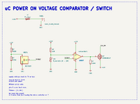
I am trying to design a way to sense voltage in a car which will switch on a microcontroller which has other tasks if a voltage is over 13.5V ( when the alternator is active in the car )
I could leave the micro controller on and monitor the voltage in a low power mode but I am looking into other ways using a comparator to see if it can use less standby power.
the relatively cheap REF30xx uses quite a Low IQ: 42 µA (Typical) and can deliver up to 25mA of current.
I am not sure how much peek current is required at the mosfet ZXMN2B01F or at least I don't know how to calculate that from the datasheet.
I am assuming I would need to use values in the resistor divider to allow for this switch on current.
That would be the burn current in standby waiting for the 13.5V before micro is switched on.
If this lost power lost in the resistor divider > 12mA then maybe I should just leave the micro controller on in low power with the screen off !!
the micro controllers other tasks would act as a timer before switching on a alternator powered DCDC charger for aux battery in the vehicle.
There is also a solar charger and charging is switched by micro controller from solar to alternator charge with a mosfet and a relay. the default
relay position with no power is solar.
so my question is is , how do I calculate the peak mosfet required power at gate. and / or is there a better way to do this ?


