Continue to Site

Welcome to EDAboard.com

Welcome to our site! EDAboard.com is an international Electronics Discussion Forum focused on EDA software, circuits, schematics, books, theory, papers, asic, pld, 8051, DSP, Network, RF, Analog Design, PCB, Service Manuals... and a whole lot more! To participate you need to register. Registration is free. Click here to register now.

Very Simple audio amplifier design experiment

Status
Not open for further replies.
my question as to why the capacitor accross RE causes more distortion is not answered fully.
I believe it has been exactly answered by LvW in post #12. The capacitor cancels the negative feedback provided by the emitter resistor. The capacitor doesn't cause the distortion. Distortion is caused by the nonlinear transistor characteristic and reduced by negative feedback.
 
  • Like
Reactions: CataM

    CataM

    Points: 2
    Helpful Answer Positive Rating
In a nutshell - current flows in and out of the capacitor but the amounts are not equal. The discharge is fairly constant (follows normal CR discharge curve) through the resistor in parallel with it but the charge path has to come through the transistor and varies with the signal you are amplifying. It creates a skew in the amplification of the rising and falling edges of the waveform.

Brian.
 

A transistor with a capacitor "AC shorting" its emitter resistor so that it has maximum gain produces a lot of distortion when its output level is high. When the capacitor is removed or has a resistor in series with it then the gain and distortion are reduced by the negative feedback produced by the emitter resistor.

In my simulation the emitter capacitor is 10uF ands at 1khz it has a reactance of 16 ohms so it has a tiny signal across it. The signal across the capacitor does not have different rising and falling edges and appears as a pretty good sinewave with very low distortion (the collector signal is still very distorted), but is leaning towards the left side a little due to its phase shift.

Does anybody use a transistor as an audio amplifier anymore when an inexpensive opamp with almost no distortion can produce as much gain as you want? But I guess a transistor with very low noise and a very low output level is used sometimes as a preamp. Then its distortion is tolerable.
 
It is never as simple as it seems.

- - - Updated - - -
 

Attachments

  • bypass_cap.png
    bypass_cap.png
    55.8 KB · Views: 90

It is never as simple as it seems.
Your distortion is 100 times higher than hi-fi but is much lower than mine because your output level is much less than mine and you are feeding the input through a series resistor that creates a current signal input instead of my voltage signal input.

When you increased the emitter capacitor value 100 times then I am surprised that the output level did not increase much.
 

Fortunately, designers have a few more tricks to improve matters.

If we replace the collector resistor with a simple current source and add some shunt feedback as well we can get 36 dB gain with a distortion level under 1%. It is not audiophile stuff but good enough for government work!
 

Attachments

  • ser_sht_conI.png
    ser_sht_conI.png
    36.4 KB · Views: 83
What is the distortion of your latest circuit if you increase the input signal so that the output level is 2.5V peak a little below clipping like mine instead of only 0.7V peak?
 

Here are the comparisons. I limited the output to 5 Vp-p since your circuit had trouble going above this level while driving into the 10 k load.

The improvement is substantial 2.57% from 16.6 % distortion. However, more interesting is the shunt only feedback with current source. At 5 Vp-p, it was down to 1.6 %. If you limit the output swing to 2.5 Vp-p, you are rewarded with 0.2 % distortion.

- - - Updated - - -

I also tested your circuit with limited output swing to 2.5 Vp-p but the distortion only dropped to 8.44 %.

- - - Updated - - -

If we make the current source better, then we can get about 0.6 % distortion for a 5 Vp-p swing.
 

Attachments

  • serie_ssI_comp.png
    serie_ssI_comp.png
    63.1 KB · Views: 93
  • shunt_5V.png
    shunt_5V.png
    64.1 KB · Views: 88
  • betterI.png
    betterI.png
    33.4 KB · Views: 83
Using an even better current source (needs two transistors now) shaved of another 0.04% while producing 38 dB gain and 5 Vp-p swing. After this, substituting the current source with an ideal one only dropped the distortion down to 0.4 %, so it seems the improvement bottomed out on this part of the circuit.

- - - Updated - - -

I also increased the input drive to 90 mVp-p for an output of 7 Vp-p, and distortion went to 0.67 %.
 

Attachments

  • betterI2.png
    betterI2.png
    31.3 KB · Views: 87
Last edited:
There is at least one more thing we can do to get better performance. Replacing the 2N3904 with a more capable 2N4401 and up the current source to 2.5 mA gives an output swing of 6.4 Vp-p, that is 36 dB gain with only 0.093 % distortion.
 

Attachments

  • betterQ.png
    betterQ.png
    57.3 KB · Views: 84
Last edited:
  • Like
Reactions: FvM

    FvM

    Points: 2
    Helpful Answer Positive Rating
Now it is very close to being "high fidelity". Adding a little more negative feedback for a little less gain will do it.
Many years ago a preamp with low distortion was made with only two transistors.
 

Attachments

  • Discrete preamp.GIF
    Discrete preamp.GIF
    19.2 KB · Views: 88
  • Like
Reactions: FvM

    FvM

    Points: 2
    Helpful Answer Positive Rating
It appears to be low gain (about 3). What is the range of input and output levels for this? Any idea of the load it could drive?
 

Now it is very close to being "high fidelity". Adding a little more negative feedback for a little less gain will do it.
Many years ago a preamp with low distortion was made with only two transistors.
Your two-transistor design is in the mainstream of discrete audio pre-amplifiers, utilizing two up to four transistors with overall feedback. They can provide stable gain, little sensitivity to parameter variations and low output impedance (if required). I think it's better to use the additional transistors as amplifier stages than current sources.
 
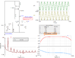
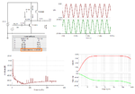
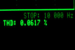
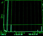
Here is a variation on the design with very good performance using ready available transistors. Tested on the bench highest harmonic was the 2nd (2 kHz) at -64.88 dB.
 

Attachments

  • 36dBaud.png
    36dBaud.png
    55.3 KB · Views: 89
  • dist1.jpg
    dist1.jpg
    52.2 KB · Views: 73
  • dist2.jpg
    dist2.jpg
    208.3 KB · Views: 77
Status
Not open for further replies.

Similar threads

Part and Inventory Search

Welcome to EDABoard.com

Sponsor

Back
Top