iamkim
Newbie level 4
Hello! Good day.
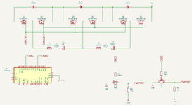
I have created an active cell balancing circuit using a resonant switched capacitor. I determined that the voltage applied to the MOSFETs was insufficient, so I used a level shifter circuit to amplify the 5V PWM frequency output from the Arduino to 11.1V to proceed with balancing. However, I observed heating and melting of the breadboard at MOSFETs connected to the middle cells, specifically at MOSFETs 3 and 4. I am unsure why the MOSFETs are overheating. During balancing, I connected three batteries in series: a 4.01V battery, a 3.895V battery, and a 3.855V battery. While balancing, I observed these heating issues, and suspect that the voltage applied to the MOSFETs is insufficient. I tried increasing the amplification circuit voltage to 18V by adjusting the power supply to 18V, setting the base resistor to 10kΩ and the collector resistor to 1kΩ. However, I measured only 7V, which is far from the expected value. Why am I measuring only 7V? I am using a PNP transistor ST2N3906. In summary, I would like to know why MOSFETs 3 and 4 in the balancing circuit are overheating, and why only 7V is measured when applying 18V in the amplification circuit. Thank you!
I have created an active cell balancing circuit using a resonant switched capacitor. I determined that the voltage applied to the MOSFETs was insufficient, so I used a level shifter circuit to amplify the 5V PWM frequency output from the Arduino to 11.1V to proceed with balancing. However, I observed heating and melting of the breadboard at MOSFETs connected to the middle cells, specifically at MOSFETs 3 and 4. I am unsure why the MOSFETs are overheating. During balancing, I connected three batteries in series: a 4.01V battery, a 3.895V battery, and a 3.855V battery. While balancing, I observed these heating issues, and suspect that the voltage applied to the MOSFETs is insufficient. I tried increasing the amplification circuit voltage to 18V by adjusting the power supply to 18V, setting the base resistor to 10kΩ and the collector resistor to 1kΩ. However, I measured only 7V, which is far from the expected value. Why am I measuring only 7V? I am using a PNP transistor ST2N3906. In summary, I would like to know why MOSFETs 3 and 4 in the balancing circuit are overheating, and why only 7V is measured when applying 18V in the amplification circuit. Thank you!