Continue to Site

Welcome to EDAboard.com

Welcome to our site! EDAboard.com is an international Electronics Discussion Forum focused on EDA software, circuits, schematics, books, theory, papers, asic, pld, 8051, DSP, Network, RF, Analog Design, PCB, Service Manuals... and a whole lot more! To participate you need to register. Registration is free. Click here to register now.

TTL waveshaping, RC networks

Status
Not open for further replies.
You may find the following helpful:

"Electrical engineers will appreciate the difficulty of nubing together a regurgitative purwell and a supramitive wennelsprock. Indeed, this proved to be a stumbling block to further development until, in 1942, it was found that the use of anhydrous nangling pins enabled a kryptonastic boiling shim to the tankered.

The early attempts to construct a sufficiently robust spiral decommutator failed largely because of a lack of appreciation of the large quasi-piestic stresses in the gremlin studs; the latter were specially designed to hold the roffit bars to the spamshaft. When, however, it was discovered that wending could be prevented by a simple addition to the living sockets, almost perfect running was secured."

Find out more about 'wending' and your faultfinding problems will be over!
 

Hello Danny,

1.) The truth table has an X for an input, what is the X? L means low , H means High , but what does X mean?
X means that the input can be high or low.

2.) Why did they are using schmitt triggers as the inputs before the NAND gate? only thing I can think of is that it cleans up the signal and creates fast edges
Yes, thats right. Normal Gates and chips don't have schmitt trriggers.

When troubleshooting multiplexers, adders, counters, gates, flip flops, how do you know the signs of a bad one? or common fails you have come across with TTL and CMOS logic chips?
First I look for the specifications of the power supply and if the LOW and HIGH voltages of Input and output are OK. These specifications I wrote in post #7. The I look for the truth table of the chips and if they do, what hey have to do.

How would you troubleshoot multiplexers, adders, counters, gates, flip flops? just to verify they are working? how would you do it?
For complex troubleshooting you need a logic analyzer.

When there is a short VCC or there is a component shorted to VCC or shorted to ground, how would you troubleshoot this?
With my eyes and my fingers. :roll: Most of shorts are make by smoothing capacitators. Look for capacitators, which are blow up. If the power supply has no current limiting. the bad device is going hot. So you can touch it.

My DVM meter doesn't measure milli-ohms to check for shorts. Is there a way to use an oscilloscope or a DVM meter to check for shorts? short to VCC or short to ground?
It's not necessary to measure milli - ohms. Look for the links which "GODFREYL" has give.

Do you troubleshoot shorts when the power is off or on and what is your approach please?
That you must calculate, what helps you to find the fault. I can not give you a direct advice.

BTW:
Do you have any experience or knowledge about electronics and digital electronics?

Regards

Rainer
 

For complex troubleshooting you need a logic analyzer.

What are some common things to look for when troubleshooting on a logic analyzer?

Mostly when I used at work a logic analyzer was to look for if all the logic signals were in sync starting at the same time, had the right time intervals apart from each other, pulse widths were correct, lead and falling edges looked sharp and not rounded or slanted.

Anything else u can ad please that you visual inspecting logic signals using a logic analyzer?

If the power supply has no current limiting. the bad device is going hot. So you can touch it.

When the power supply is current limiting the Buss voltage or VCC is go Higher or lower? or is it always lower?

When the power supply is current limiting, I disconnect each stage that is connected to the Buss rail or VCC one by one until i get the powers supply voltage back to normal, Is this what you do? when the power supply is current limiting?

the bad device is going hot. So you can touch it

My DVM meter has a Temperature setting using a temperature probe, I measure the temperature of a good working circuit and compare with a bad circuit

If the temperature is higher on the IC chip, it might be a short or its around that area

Is this what you do?

BTW:
Do you have any experience or knowledge about electronics and digital electronics?

Some, I'm not the best that's why I ask questions

Thanks for your help and info btw
 

What are these flip flops and latches doing in this circuit?

Flip Flop pic#1.jpg
Flip Flop pic#2.jpg
Flip Flop pic#3.jpg
Flip Flop pic#4.jpg
Flip Flop pic#5.jpg
Flip Flop pic#6.jpg
 

Here is a 555 time with a FET on the output, what is the FET used for? i see this a lot when used with a 555 timer, they use a MosFET on the output of the 555 timer but why?

555 time with FET output.jpg
 

My work using a triangle waveform and a sine waveform to create a PWM modulation output

Take a look:
PWM modulation pic#1.jpg

What I don't understand is
1.) How does a triangle waveform and a sine waveform , the difference between the two will create a pulse width modulation waveform?

2.) I can't tell on my oscilloscope the difference between a square waveform VS a pulse width modulation waveform, they both look the same to me, so how do I tell the difference between the two?
 

My work using a triangle waveform and a sine waveform to create a PWM modulation output
...
What I don't understand is
1.) How does a triangle waveform and a sine waveform , the difference between the two will create a pulse width modulation waveform?

2.) I can't tell on my oscilloscope the difference between a square waveform VS a pulse width modulation waveform, they both look the same to me, so how do I tell the difference between the two?

The triangle waveform needs to be at a much faster frequency than the sine wave.


- - - Updated - - -

Here is a 555 time with a FET on the output, what is the FET used for? i see this a lot when used with a 555 timer, they use a MosFET on the output of the 555 timer but why?

View attachment 89329

The 555 can only source (or sink) a small amount of current. It is only sufficient to drive low-power devices.

However if the next device requires too much current, then you have to install a transistor/ FET/ mosfet, etc., to provide the needed power.
 

I Don't understand how the HIGH state and LOW state of the pwm get compared, at what levels do they get compared at?

- - - Updated - - -

I Don't understand how the HIGH state and LOW state of the pwm get compared, at what levels do they get compared at?
 

I Don't understand how the HIGH state and LOW state of the pwm get compared, at what levels do they get compared at?

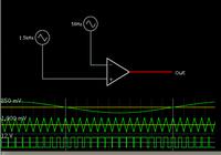
The op amp is a comparator and is at maximum gain. Its output alternates between the positive and negative rails, depending on which of the two waveforms has greater amplitude than the other, at any instant.

See if an animated simulation conveys the action better. Click the link below. It will open the simulator at falstad.com/circuit, load my schematic similar to post #27, and run it on your computer.

https://tinyurl.com/b9ofw4g

Change the speed and amplitudes of the waveforms. (Right-click a waveform generator, and select Edit, to bring up an edit window.)

Slow down the triangle wave. The PWM will have a coarser resolution.

Try reducing the triangle's amplitude. There will be a point where it no longer exceeds the sinewave.
 

Status
Not open for further replies.

Similar threads

Part and Inventory Search

Welcome to EDABoard.com

Sponsor

Back
Top