Welcome to our site! EDAboard.com is an international Electronics Discussion Forum focused on EDA software, circuits, schematics, books, theory, papers, asic, pld, 8051, DSP, Network, RF, Analog Design, PCB, Service Manuals... and a whole lot more! To participate you need to register. Registration is free. Click here to register now.
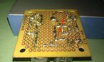
Eureka!!!! It Works!!!! Your the freakin' greatest! Should I upgrade any of the components? Maybe get some stronger pots, because I can see it spark inside. They are 50vdc/0.1W. They're really sensitive to trim too, since I only need about 5 seconds.
Normally the pots need to be series with a small resistor just to prevent adjusting near to zero value (sparks inside due to charged capacitors). Now if the timing are OK you can measure the value of the pots and to replace them with some fixed resistors. (Just to avoid any changes of the circuit adjustments in the car).
I’m glad we have finally found out our problem.
Thank you so much for your help mister_rf! I LITERALLY could not have done this without you! I'm going to assemble everything onto a circuit board. I'll post a pick when I'm done. I really appreciate all the time and effort you invested in helping me with this.
Simple.
As an approximation of the doubling time delay need doubling resistor value (1k, 2.2k, 3.3k, 4.7k and so on). You already have some 4.7k spare resistors, use them instead of the pots and check the results.
Thanks. There's a lot more space between there than it seems in the picture. I might have to do it over anyway because its not working now. Relay won't activate. It did for a second, then it stopped. I've been going over it, trying to see if I missed a connection or something, but no luck. I just put it aside for a while cause I was up for hours trying to figure it out. Figured I'd come back to it with fresh eyes. Then I may see if I did something wrong. Other possibility is something went bad from constant heat (which I think is the case). Either way I'll figure it out and correct it. Either the pots or transistors. But I'll probably replace everything just in case. Thanks again for all your help mister_rf!!!
---------- Post added at 21:39 ---------- Previous post was at 21:32 ----------
Also, if I want to make the connection process easier by going with the BDW transistors, so I can do away with the 2 smaller transistors, could you please show me the layout for that?
This site uses cookies to help personalise content, tailor your experience and to keep you logged in if you register.
By continuing to use this site, you are consenting to our use of cookies.


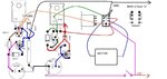


 take care of ‘’cross wires’’, need to consider isolating that piece of wire.
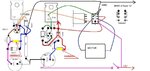