Kgonz
Newbie level 5
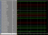
Hello I am trying to create a testbench for this VHDL code of an SPI slave that I found online for verification and so that i can implement it into a project that I'm working on. I've gotten my testbench to compile and run and to drive signals but the data transfer and all the MOSI and MISO lines aren't working the way the author verified it in the website. any help is appreciated. the author verified through the website so I know the reason it doesn't work has to do with the testbench i wrote
this is a link to the website where I got the SPI slave
https://forum.digikey.com/t/spi-slave-vhdl/12721
SPI SLAVE
SPI Slave TestBench
this is a link to the website where I got the SPI slave
https://forum.digikey.com/t/spi-slave-vhdl/12721
SPI SLAVE
- --------------------------------------------------------------------------------
- --
- -- FileName: spi_slave.vhd
- -- Dependencies: none
- -- Design Software: Quartus Prime Version 17.0.0 Build 595 SJ Lite Edition
- --
- -- HDL CODE IS PROVIDED "AS IS." DIGI-KEY EXPRESSLY DISCLAIMS ANY
- -- WARRANTY OF ANY KIND, WHETHER EXPRESS OR IMPLIED, INCLUDING BUT NOT
- -- LIMITED TO, THE IMPLIED WARRANTIES OF MERCHANTABILITY, FITNESS FOR A
- -- PARTICULAR PURPOSE, OR NON-INFRINGEMENT. IN NO EVENT SHALL DIGI-KEY
- -- BE LIABLE FOR ANY INCIDENTAL, SPECIAL, INDIRECT OR CONSEQUENTIAL
- -- DAMAGES, LOST PROFITS OR LOST DATA, HARM TO YOUR EQUIPMENT, COST OF
- -- PROCUREMENT OF SUBSTITUTE GOODS, TECHNOLOGY OR SERVICES, ANY CLAIMS
- -- BY THIRD PARTIES (INCLUDING BUT NOT LIMITED TO ANY DEFENSE THEREOF),
- -- ANY CLAIMS FOR INDEMNITY OR CONTRIBUTION, OR OTHER SIMILAR COSTS.
- --
- -- Version History
- -- Version 1.0 7/5/2012 Scott Larson
- -- Initial Public Release
- -- Version 1.1 11/27/2012 Scott Larson
- -- Added an asynchronous active low reset
- -- Version 1.2 5/7/2019 Scott Larson
- -- Modified architecture slightly to make it synthesizable with more tools
- --
- --------------------------------------------------------------------------------
- LIBRARY ieee;
- USE ieee.std_logic_1164.all;
- USE ieee.std_logic_arith.all;
- ENTITY spi_slave IS
- GENERIC(
- cpol : STD_LOGIC := '0'; --spi clock polarity mode
- cpha : STD_LOGIC := '0'; --spi clock phase mode
- d_width : INTEGER := 8); --data width in bits
- PORT(
- sclk : IN STD_LOGIC; --spi clk from master
- reset_n : IN STD_LOGIC; --active low reset
- ss_n : IN STD_LOGIC; --active low slave select
- mosi : IN STD_LOGIC; --master out, slave in
- rx_req : IN STD_LOGIC; --'1' while busy = '0' moves data to the rx_data output
- st_load_en : IN STD_LOGIC; --asynchronous load enable
- st_load_trdy : IN STD_LOGIC; --asynchronous trdy load input
- st_load_rrdy : IN STD_LOGIC; --asynchronous rrdy load input
- st_load_roe : IN STD_LOGIC; --asynchronous roe load input
- tx_load_en : IN STD_LOGIC; --asynchronous transmit buffer load enable
- tx_load_data : IN STD_LOGIC_VECTOR(d_width-1 DOWNTO 0); --asynchronous tx data to load
- trdy : BUFFER STD_LOGIC := '0'; --transmit ready bit
- rrdy : BUFFER STD_LOGIC := '0'; --receive ready bit
- roe : BUFFER STD_LOGIC := '0'; --receive overrun error bit
- rx_data : OUT STD_LOGIC_VECTOR(d_width-1 DOWNTO 0) := (OTHERS => '0'); --receive register output to logic
- busy : OUT STD_LOGIC := '0'; --busy signal to logic ('1' during transaction)
- miso : OUT STD_LOGIC := 'Z'); --master in, slave out
- END spi_slave;
- ARCHITECTURE logic OF spi_slave IS
- SIGNAL mode : STD_LOGIC; --groups modes by clock polarity relation to data
- SIGNAL clk : STD_LOGIC; --clock
- SIGNAL bit_cnt : STD_LOGIC_VECTOR(d_width+8 DOWNTO 0); --'1' for active transaction bit
- SIGNAL wr_add : STD_LOGIC; --address of register to write ('0' = receive, '1' = status)
- SIGNAL rd_add : STD_LOGIC; --address of register to read ('0' = transmit, '1' = status)
- SIGNAL rx_buf : STD_LOGIC_VECTOR(d_width-1 DOWNTO 0) := (OTHERS => '0'); --receiver buffer
- SIGNAL tx_buf : STD_LOGIC_VECTOR(d_width-1 DOWNTO 0) := (OTHERS => '0'); --transmit buffer
- BEGIN
- busy <= NOT ss_n; --high during transactions
- --adjust clock so writes are on rising edge and reads on falling edge
- mode <= cpol XOR cpha; --'1' for modes that write on rising edge
- WITH mode SELECT
- clk <= sclk WHEN '1',
- NOT sclk WHEN OTHERS;
- --keep track of miso/mosi bit counts for data alignmnet
- PROCESS(ss_n, clk)
- BEGIN
- IF(ss_n = '1' OR reset_n = '0') THEN --this slave is not selected or being reset
- bit_cnt <= (conv_integer(NOT cpha) => '1', OTHERS => '0'); --reset miso/mosi bit count
- ELSE --this slave is selected
- IF(rising_edge(clk)) THEN --new bit on miso/mosi
- bit_cnt <= bit_cnt(d_width+8-1 DOWNTO 0) & '0'; --shift active bit indicator
- END IF;
- END IF;
- END PROCESS;
- PROCESS(ss_n, clk, st_load_en, tx_load_en, rx_req)
- BEGIN
- --write address register ('0' for receive, '1' for status)
- IF(bit_cnt(1) = '1' AND falling_edge(clk)) THEN
- wr_add <= mosi;
- END IF;
- --read address register ('0' for transmit, '1' for status)
- IF(bit_cnt(2) = '1' AND falling_edge(clk)) THEN
- rd_add <= mosi;
- END IF;
- --trdy register
- IF((ss_n = '1' AND st_load_en = '1' AND st_load_trdy = '0') OR reset_n = '0') THEN
- trdy <= '0'; --cleared by user logic or reset
- ELSIF(ss_n = '1' AND ((st_load_en = '1' AND st_load_trdy = '1') OR tx_load_en = '1')) THEN
- trdy <= '1'; --set when tx buffer written or set by user logic
- ELSIF(falling_edge(clk)) THEN
- IF(wr_add = '1' AND bit_cnt(9) = '1') THEN
- trdy <= mosi; --new value written over spi bus
- ELSIF(rd_add = '0' AND bit_cnt(d_width+8) = '1') THEN
- trdy <= '0'; --clear when transmit buffer read
- END IF;
- END IF;
- --rrdy register
- IF((ss_n = '1' AND ((st_load_en = '1' AND st_load_rrdy = '0') OR rx_req = '1')) OR reset_n = '0') THEN
- rrdy <= '0'; --cleared by user logic or rx_data has been requested or reset
- ELSIF(ss_n = '1' AND st_load_en = '1' AND st_load_rrdy = '1') THEN
- rrdy <= '1'; --set when set by user logic
- ELSIF(falling_edge(clk)) THEN
- IF(wr_add = '1' AND bit_cnt(10) = '1') THEN
- rrdy <= mosi; --new value written over spi bus
- ELSIF(wr_add = '0' AND bit_cnt(d_width+8) = '1') THEN
- rrdy <= '1'; --set when new data received
- END IF;
- END IF;
- --roe register
- IF((ss_n = '1' AND st_load_en = '1' AND st_load_roe = '0') OR reset_n = '0') THEN
- roe <= '0'; --cleared by user logic or reset
- ELSIF(ss_n = '1' AND st_load_en = '1' AND st_load_roe = '1') THEN
- roe <= '1'; --set by user logic
- ELSIF(falling_edge(clk)) THEN
- IF(rrdy = '1' AND wr_add = '0' AND bit_cnt(d_width+8) = '1') THEN
- roe <= '1'; --set by actual overrun
- ELSIF(wr_add = '1' AND bit_cnt(11) = '1') THEN
- roe <= mosi; --new value written by spi bus
- END IF;
- END IF;
- --receive registers
- --write to the receive register from master
- IF(reset_n = '0') THEN
- rx_buf <= (OTHERS => '0');
- ELSE
- FOR i IN 0 TO d_width-1 LOOP
- IF(wr_add = '0' AND bit_cnt(i+9) = '1' AND falling_edge(clk)) THEN
- rx_buf(d_width-1-i) <= mosi;
- END IF;
- END LOOP;
- END IF;
- --fulfill user logic request for receive data
- IF(reset_n = '0') THEN
- rx_data <= (OTHERS => '0');
- ELSIF(ss_n = '1' AND rx_req = '1') THEN
- rx_data <= rx_buf;
- END IF;
- --transmit registers
- IF(reset_n = '0') THEN
- tx_buf <= (OTHERS => '0');
- ELSIF(ss_n = '1' AND tx_load_en = '1') THEN --load transmit register from user logic
- tx_buf <= tx_load_data;
- ELSIF(rd_add = '0' AND bit_cnt(7 DOWNTO 0) = "00000000" AND bit_cnt(d_width+8) = '0' AND rising_edge(clk)) THEN
- tx_buf(d_width-1 DOWNTO 0) <= tx_buf(d_width-2 DOWNTO 0) & tx_buf(d_width-1); --shift through tx data
- END IF;
- --miso output register
- IF(ss_n = '1' OR reset_n = '0') THEN --no transaction occuring or reset
- miso <= 'Z';
- ELSIF(rising_edge(clk)) THEN
- IF(rd_add = '1') THEN --write status register to master
- CASE bit_cnt(10 DOWNTO 8) IS
- WHEN "001" => miso <= trdy;
- WHEN "010" => miso <= rrdy;
- WHEN "100" => miso <= roe;
- WHEN OTHERS => NULL;
- END CASE;
- ELSIF(rd_add = '0' AND bit_cnt(7 DOWNTO 0) = "00000000" AND bit_cnt(d_width+8) = '0') THEN
- miso <= tx_buf(d_width-1); --send transmit register data to master
- END IF;
- END IF;
- END PROCESS;
- END logic;
SPI Slave TestBench
- library IEEE;
- use IEEE.Std_logic_1164.all;
- entity spi_slavetestbench is
- end spi_slavetestbench;
- architecture bench of spi_slavetestbench is
- component spi_slave
- port
- (sclk, reset_n,ss_n,mosi,rx_req,st_load_en,st_load_trdy,st_load_rrdy,st_load_roe,tx_load_en: in std_logic;
- tx_load_data : IN STD_LOGIC_VECTOR;
- rx_data : OUT STD_LOGIC_VECTOR;
- busy, miso : out std_logic;
- trdy,rrdy,roe : BUFFER std_logic
- );
- end component;
- constant d_width : INTEGER := 8;
- signal sclk, reset_n,ss_n,mosi,rx_req,st_load_en,st_load_trdy,st_load_rrdy,st_load_roe,tx_load_en: std_logic;
- signal busy, miso: std_logic;
- signal tx_load_data: STD_LOGIC_VECTOR(d_width-1 DOWNTO 0);
- signal rx_data : STD_LOGIC_VECTOR(d_width-1 DOWNTO 0) := (OTHERS => '0');
- signal trdy,rrdy,roe : std_logic;
- constant clock_period: time := 10 ns;
- SIGNAL mode : STD_LOGIC; --groups modes by clock polarity relation to data
- SIGNAL clk : STD_LOGIC; --clock
- SIGNAL bit_cnt : STD_LOGIC_VECTOR(d_width+8 DOWNTO 0); --'1' for active transaction bit
- SIGNAL wr_add : STD_LOGIC; --address of register to write ('0' = receive, '1' = status)
- SIGNAL rd_add : STD_LOGIC; --address of register to read ('0' = transmit, '1' = status)
- SIGNAL rx_buf : STD_LOGIC_VECTOR(d_width-1 DOWNTO 0) := (OTHERS => '0'); --receiver buffe SIGNAL tx_buf : STD_LOGIC_VECTOR(d_width-1 DOWNTO 0) := (OTHERS => '0'); --transmit buffer
- signal stop_the_clock: boolean;
- begin
- DUT : entity work.spi_slave
- port map (
- sclk => sclk,
- reset_n => reset_n,
- ss_n => ss_n,
- mosi => mosi,
- rx_req => rx_req,
- st_load_en => st_load_en,
- st_load_trdy => st_load_trdy,
- st_load_rrdy => st_load_rrdy,
- st_load_roe => st_load_roe,
- tx_load_en => tx_load_en,
- tx_load_data => tx_load_data,
- rx_data => rx_data,
- busy => busy,
- trdy => trdy,
- rrdy => rrdy,
- roe => roe,
- miso => miso
- );
- STIM: process -- stimulus
- begin
- wait for clock_period;
- reset_n <= '1';
- ss_n <= '1';
- wait for clock_period;
- reset_n <= '1';
- ss_n <= '0';
- tx_load_en <= '1';
- tx_load_data <= "10101010";
- wait for clock_period*40;
- stop_the_clock <= true;
- wait;
- end process;
- process -- clock generation
- begin
- while not stop_the_clock loop
- clk <= '0';
- wait for clock_period / 2;
- clk <= '1';
- wait for clock_period / 2;
- end loop;
- wait;
- end process;
- process -- clock generation
- begin
- while not stop_the_clock loop
- sclk <= '0';
- wait for clock_period / 2;
- sclk <= '1';
- wait for clock_period / 2;
- end loop;
- wait;
- end process;
- end;