Continue to Site

Welcome to EDAboard.com

Welcome to our site! EDAboard.com is an international Electronics Discussion Forum focused on EDA software, circuits, schematics, books, theory, papers, asic, pld, 8051, DSP, Network, RF, Analog Design, PCB, Service Manuals... and a whole lot more! To participate you need to register. Registration is free. Click here to register now.

[SOLVED] TEK TDS320 ch2 trace is off 2 minutes after POWER is ON

Status
Not open for further replies.
Brad,

Your answer was like a cold water bath :cry:

I press, I flex, I twist with no avail.

But when I am using the ice cube, I have to press down the ice firmly and a good couple of seconds in order to bring back the CH2 trace in the display, which lead me to think that something was loose (wich I couldn't confirm pressing and twisting the chip and the board).

Also this particular chip senses to my finger has hotter than the rest of the other chips around (with exception of the chips in the hybrid input attenuator that both channels chips run equal or hotter than this one) in the main board.

But the higher voltage in any of its pins is +4.99V...

At the moment don't know what to think or if I invest more time in this.

This particular chip is a "IC ASIC:BIPOLAR, Linear, channels switch" , could some parasitic capacitance be held responsible for the CH2 switch off?

Also do you have any clue regarding the identification of the component you point (the one looking like a big cap with the side tinted red)??
 

UPDATE!!!

I found that I don't need the ice cube to recover the CH2 trace, I just have to press down the chip with all my thumb.

I try to press down the chip mainly in its four boundaries with no avail, also try to press down the pcb board with the pressure point near the chip also with no avail.

This mean that stressing the pcb board down didn't recover the trace

This also means that the problem is not a heat related one, my thumb is not a cold alu heat cooler.

Now, What could be wrong?

I hope the problem don't rely in underneath the chip or worst, in the inner layers of the pcb underneath the chip.

After this events, the scope work well for two sessions and then for the third CH2 trace was off...


UPDATE2!!!

If I press slightly in the center of the chip with the blunt point of a pencil, pins 30 and 31 change their voltage and the CH2 trace return to the display.


Any idea of what to do next?
 
Last edited:

Also this particular chip senses to my finger has hotter than the rest of the other chips around (with exception of the chips in the hybrid input attenuator that both channels chips run equal or hotter than this one) in the main board.

But the higher voltage in any of its pins is +4.99V...

At the moment don't know what to think or if I invest more time in this.

This particular chip is a "IC ASIC:BIPOLAR, Linear, channels switch" , could some parasitic capacitance be held responsible for the CH2 switch off?

Perhaps you're thinking of parasitic oscillations? Yes, something like that could heat up the IC. And it would not necessarily pull down the supply rail.

And such oscillations tend to be unpredictable. The scope recently worked for several hours with no problem.

It would be great to have an oscilloscope to fix an oscilloscope, wouldn't it?

If the chip gets hotter than the others, then it's possible the problem starts outside the chip, heating it up.

One would think it's a power supply problem. However there's the fact that only CH2 is affected.

There is also the fact that the trace moves upward smoothly off the screen. If a wire were getting disconnected inside the chip or outside the chip, we would expect the trace to disappear suddenly.

There only seems to be one of that IC. So it serves both channels. But only one channel is malfunctioning. Could there be twin groups of components, one serving CH1 and one serving CH2? I don't spot such groups on the visible side of the board. If you can locate such twin groups, then you might compare volt readings at corresponding points.

At the moment don't know what to think or if I invest more time in this.

Yes, you have checked the things that one checks first. From here you could be in for a lot of tedious effort, and may never diagnose the problem.

If it's the IC, since it has many pins on each edge, then replacing it will be an ordeal. And the company is likely to charge you an arm and a leg.

Although the scope was in pristine condition, it was still 'used'. It may have been a returned item.

Also do you have any clue regarding the identification of the component you point (the one looking like a big cap with the side tinted red)??

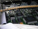
Sorry, I am inexperienced with surface-mount components. The one I circled stood out because it doesn't look like the others.
 
Brad,

Did you read my updates above, my recent findings change all the scenario of analysis of the problem.

I would like to know your opinion/thoughts in regard to the recent findings.

Thanks.
 

UPDATE!!!

I found that I don't need the ice cube to recover the CH2 trace, I just have to press down the chip with all my thumb.

I try to press down the chip mainly in its four boundaries with no avail, also try to press down the pcb board with the pressure point near the chip also with no avail.

This mean that stressing the pcb board down didn't recover the trace

This also means that the problem is not a heat related one, my thumb is not a cold alu heat cooler.

Now, What could be wrong?

I hope the problem don't rely in underneath the chip or worst, in the inner layers of the pcb underneath the chip.

After this events, the scope work well for two sessions and then for the third CH2 trace was off...


UPDATE2!!!

If I press slightly in the center of the chip with the blunt point of a pencil, pins 30 and 31 change their voltage and the CH2 trace return to the display.


Any idea of what to do next?

I posted a message in response to the above, then I had to away from the computer, but my post didn't go through, apparently.

Good work. Perseverance pays off. This is headway you've made, and on your own initiative.

Your next step is to open up the housing and perform surgery on the chip inside. Just joking. I have never heard of anyone doing such a thing, but if I had, I'd refer you to him for a briefing on how to proceed.

You have found where to apply pressure to fix the problem. This pressure either (a) goes directly onto the chip inside (if it is rigidly encased), or (b) it is transferred to the outer area and to one or more pin connections inside the IC, or (c) the pressure is transferred to the chip indirectly.

Small chips probably can be rigidly encased in a plastic housing. However when a chip is large enough, I believe it sits in a cavern. From your description, it is not a rigid plastic housing. You can press down on it to fix the problem, yet not break it.

If you're lucky you can find the spot where the least pressure will fix CH2. Then you'll fasten a jig in place to maintain pressure continually.

The least pressure fix might be from underneath the IC. However it's risky because too much pressure is almost guaranteed to break the chip.

Or the least pressure fix might be by lifting the IC, or lifting from underneath the circuit board.

Or a spot where you press down on a pin. Have you pressed down on every pin? Have you examined with a strong magnifier at every pin, to look for a hairline *****? As an alternate you can re-melt the solder joint at each pin.

Or press inward on each pin. Or flex/twist each pin a little. This might restore broken contact with the gold wire inside.

OTOH you don't know when you'll make the problem worse. Therefore don't apply max pressure to anything right away. First go the rounds to every spot with little pressure. If that doesn't help then go around with medium pressure. Etc.

You don't know the thickness of plastic covering the chip. Avoid pressing with a steel tool on the top or bottom of the IC. It is liable to break through the casing and smash into the chip.

Eventually there could be the step of sawing (or using a small grinding wheel) to remove plastic starting at the outer edge, until you encounter the inner chamber where the chip is. You may never reach this point, of course, It's a final resort if nothing else works.
 

Brad,

Yesterday, tinkering with the chip I found that a light pressure in a specific spot (right between the k of tek word and the u of the us word, check the chip pic) would bring on the CH2 trace.

So yesterday night I made a jig with some barbecue wood sticks and installed it in a particular way to apply enough pressure to revive CH2 trace.

Here it is:

DSCN2817_2.JPG

So although unorthodox we have here a FULLY working Oscilloscope.

Many thanks to you Brad (and also for Albert) you really help me diagnose the problem of the scope.

The solution found isn't beautiful, but it is a solution that do work.

Brad, You are a valorous member of this board.

Thank you!
 

Really fantastic.
Your triumph is my triumph.
To be valorous is worth aspiring to.

Considering that it is often a little thing that's wrong, it seemed only right to put in the effort to track it down.

My scope is a Tektronix RM504. Tube type. I had to do some detective work on it. I managed to fix it. Later I was able to fix my buddy's identical scope the same way. We had gotten them from a used electronics shop a few years previous. So by fixing two scopes that was multiple returns for my work.
 

Status
Not open for further replies.

Part and Inventory Search

Welcome to EDABoard.com

Sponsor

Back
Top