Continue to Site

Welcome to EDAboard.com

Welcome to our site! EDAboard.com is an international Electronics Discussion Forum focused on EDA software, circuits, schematics, books, theory, papers, asic, pld, 8051, DSP, Network, RF, Analog Design, PCB, Service Manuals... and a whole lot more! To participate you need to register. Registration is free. Click here to register now.

Switching regulator peak current

Status
Not open for further replies.
presumably the audio you heard was at the same frequency as the pulsing of your load...?
 
  • Like
Reactions: Zak28

    Zak28

    Points: 2
    Helpful Answer Positive Rating
It wasn't the same frequency rather constant buzzing with periodic higher amplitude peaks however it was very low and simply holding the pcb often caused enough flexture or rigidity to remove the noise. I suppose if the board were fastened with screws it would not make noise.

For an output of 2.5mA and ~27V is a 100uH simply too large for this boost IC or are there better inductor values for this output?
 

100uH is not too large - it will get you into CCM - you may notice the diode runs a bit warmer to to rev recovery losses at 1200kHz
 
  • Like
Reactions: Zak28

    Zak28

    Points: 2
    Helpful Answer Positive Rating
Therefore with an average of 111mA is nearly any 1amp inductor good enough or is the peak current really the determinant for the inductor selection?
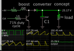
My simulation agrees with previous posts estimating that at 1 MHz a 7uH inductor has peak current at 500 mA or so. Therefore your inductor can be rated for saturation at 500mA. However power rating (heat endurance) is a different parameter which is influenced by several factors, and which needs adequate safety margin.

This screenshot has a higher Henry value (25uH) to illustrate how it permits reduced Ampere levels (as compared to the 6.8uH design).

boost conv clk-driv 1MHz 25uH 8VDC supply 700 ohm load gets 25V.png

Output is 25V. Spec current draw is 25mA. This calculates to 1k ohm load. To create 70 percent efficiency I reduced load resistance from 1k to 700 ohms.

Does this imply CCM - a state were there is only an average current in the inductor is the least wasteful state of the boost converter?

CCM allows use of an inductor with lower saturation rating, due to less amplitude of current peaks.

Wasted power rises as the square of Amperes. DCM means high current peaks, hence greater I^2 * R losses.
 
  • Like
Reactions: Zak28

    Zak28

    Points: 2
    Helpful Answer Positive Rating
The diode in the fabbed board and is PMEG3050EP which is very efficient.

https://assets.nexperia.com/documents/data-sheet/PMEG3050EP.pdf

Also the input and output capacitors are a pair of X5R 1206 10uF CL31A106KBHNNNE

www.samsungsem.com/kr/support/produ.../afieldfile/2019/05/10/19-CL31A106KBHNNNE.pdf

The mt3608 boost converter datasheet suggests a single 22uF for input and output however - does a pair of the 10uF capacitors improve the efficiency in the boost converter, especially if the converter was set to output more current?
 

Status
Not open for further replies.

Similar threads

Part and Inventory Search

Welcome to EDABoard.com

Sponsor

Back
Top