Continue to Site

Welcome to EDAboard.com

Welcome to our site! EDAboard.com is an international Electronics Discussion Forum focused on EDA software, circuits, schematics, books, theory, papers, asic, pld, 8051, DSP, Network, RF, Analog Design, PCB, Service Manuals... and a whole lot more! To participate you need to register. Registration is free. Click here to register now.

SPI Slave with strange behavior

Status
Not open for further replies.
sounds like a classical case of miscalculated output load, no? the ASIC chip cannot drive the line. Some screenshots even showed the curvy line suggesting a capacitive behavior (discharging).
 

I can not reveal the name of the people I am working with, they allow me to investigate and search for help on my own but with some restrictions (like I can not show the code to anyone and I can not reveal the company identity).
I don't really know what they will do differently in the bounding process, they just tell me in a meeting this afternoon, after I share with them my conclusions and results, that they will do two or three more chips bounded more carefully for me to test. As soon as I get my hands on them I will test them and share with you my results.

Never expected to know the company identity or the code used (I'm sure others were not expecting this either, given this is an ASIC design).

I'd bet a beer this "bounded more carefully" is their attempt to either leave out a bond wire or make a bond wire with some kind of loop in it to avoid the other bond wire. I'm not impressed with either option.

I'd also wager a shot of whiskey to go along with that beer, that the company doing such a hack job is in a large Asian country well known for minimal quality work.

After working on this job you'll probably need to that Boilermaker.

- - - Updated - - -

sounds like a classical case of miscalculated output load, no? the ASIC chip cannot drive the line. Some screenshots even showed the curvy line suggesting a capacitive behavior (discharging).

The fact that the vendor thinks that "bounding" can potentially fix the problem doesn't seem to jive with an output load problem, or maybe I'm just being overly cynical.
 

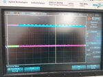
So there is for sure some problem in the MISO pin, I did the pull up resistor test with a 10k resistor and the result was this. (the color schematic is the same: sclk in yellow, MOSI in green, MISO in blue and CS in pink)

IMG_20180611_180307.jpg

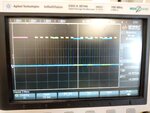
The MISO pin, according to the verilog code that I have is always being driven to zero, or in the case of the read operation, driven by the data the slave wants to send. what is happening is that the line is not being driven at all. The same test in the FPGA worked perfectly (image bellow).

IMG_20180612_090859.jpg

I will share these results with them and wait for the new bounded chips to arrive.
The strange part is that I am also not able to correctly write (I can write a 3 to register zero to turn on the analog part of the circuit but when I do so, nothing happens) although there seams to be no problem in the MOSI line.
 

Hi,

It seems MISO is not driven at all.
* Maybe wrong pin location (cross check the output files after compilation with your wiring and the IC pin naming)
* maybe bad soder joint
* maybe wrong code (driver enable not correct?)
* maybe defective IC
* maybe defective pin driver
* global output enable not active?
* global reset active?
* power supply for all sections correct?
(in my eyes: "MISO driven LOW while CS=1" is wrong, too. It needs to be high_impedance to comply with SPI.)

MOSI:
Difficult do see if it´s working correctly, because - as an input - pin it behaves passively.
For debugging you may modify your to in a way that the signal is routed to another pin (currently unused pin or MISO).

Klaus
 

I wonder what is the DFT scan for logic defection test. Did they confirm this ?
This could be bounding issue or internal logic defection issue.
 

They don't have DFT scan logic in the chip. I am still waiting for the new bounded chips, the one that I was using had a bounding problem on the digital ground.
As soon as I get my hands on the new chips I will do some tests and share the results with you.
 

Status
Not open for further replies.

Part and Inventory Search

Welcome to EDABoard.com

Sponsor

Back
Top