Continue to Site

Welcome to EDAboard.com

Welcome to our site! EDAboard.com is an international Electronics Discussion Forum focused on EDA software, circuits, schematics, books, theory, papers, asic, pld, 8051, DSP, Network, RF, Analog Design, PCB, Service Manuals... and a whole lot more! To participate you need to register. Registration is free. Click here to register now.

Solution for Hard reset ATMEA328P

Status
Not open for further replies.

johnny78

Full Member level 5
Full Member level 5
Joined
Jun 28, 2017
Messages
270
Helped
1
Reputation
2
Reaction score
5
Trophy points
1,298
Visit site
Activity points
3,469
hi Guys
i need to Disable my circuit in case of Emergerncy for some reasons
But how can i decide which its restarted after Hard reset or normal power on ?
i need to do some tasks in case the emergenct button was pressed & released
any idea please ?
is it possible to save a variable to Eeprom in the case of hard reset ?

thanks
Johnny
 

im planning to use Avrisp & im reading about reuse Assembly
But i will read once more about easy way with bootloader

thanks
Johnny
--- Updated ---


i think it means Enabled or 0

i didnt yet

i didnt use Assembly for atmel before but im trying to reuse it
im reading about it now
thanks
Depending on chip some B/Ls initialize clock circuits, turn on power in other
circuits, etc... so be aware of that. Thats why an examination of what chip
needs to startup prudent.

Regards, Dana.
--- Updated ---

Some interesting questions about Optiboot -


Looks like it avoids any chip setup other than serial....

Using / Programming Optiboot -


Regards, Dana.
--- Updated ---

If you start using a lot of Arduinos a useful programmer, cheap, like $4, is USBasp.

iu


Allows easy programming to 6 and 10 pin headers on Arduino boards.
Note there is a small adapter board to translate 10 to 6 pin, plan on
buying that as well.

On the driver page I show above are several GUI programmer utilities to
use with it. I happen to use eXtreme Burner. Makes easy to also program
fuses. But be careful when you mess with them, as you can brick your board
permanently with improper settings,. so do that with caution and manual reading.

You can also use another Arduino board to act as ISP, but not as flexible as USBasp.


Regards, Dana.
 
Last edited:

Depending on chip some B/Ls initialize clock circuits, turn on power in other
circuits, etc... so be aware of that. Thats why an examination of what chip
needs to startup prudent.

Regards, Dana.
--- Updated ---

Some interesting questions about Optiboot -


Looks like it avoids any chip setup other than serial....

Using / Programming Optiboot -


Regards, Dana.
--- Updated ---

If you start using a lot of Arduinos a useful programmer, cheap, like $4, is USBasp.

iu


Allows easy programming to 6 and 10 pin headers on Arduino boards.
Note there is a small adapter board to translate 10 to 6 pin, plan on
buying that as well.

On the driver page I show above are several GUI programmer utilities to
use with it. I happen to use eXtreme Burner. Makes easy to also program
fuses. But be careful when you mess with them, as you can brick your board
permanently with improper settings,. so do that with caution and manual reading.

You can also use another Arduino board to act as ISP, but not as flexible as USBasp.


Regards, Dana.
good morning
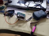
im using Avrisp & a small USB ISP programmer & sometimes Arduino as isp
i have built some shields to help me using arduino or any other programmers
& also i have bricked few chips already because of the baddest programmer i had (mikro prog AVR)
then i have built an Arduino based High voltage programmer to reset fuses

is it useful to share my tools here ?


Johnny
 

Attachments

  • Arduino Tools1.jpg
    Arduino Tools1.jpg
    10.5 KB · Views: 150
  • Arduino Tools2.jpg
    Arduino Tools2.jpg
    12.7 KB · Views: 154

good morning
im using Avrisp & a small USB ISP programmer & sometimes Arduino as isp
i have built some shields to help me using arduino or any other programmers
& also i have bricked few chips already because of the baddest programmer i had (mikro prog AVR)
then i have built an Arduino based High voltage programmer to reset fuses

is it useful to share my tools here ?


Johnny
Looks like you have key tools and have done your homework.

Good luck on the MCUSR issue, seems simple to manage now by using
latest Optiboot firmware. I installed it myself, much faster on uploads,
nice result as well as fix for MCUSAR problem.


Regards, Dana.


No on read the reg as I think the prior links to the user that did
with OptiBoot accomplished that. Coupled with fact OptiBoot
author made significant mods to his B/L to fix this exact problem.

I did not feel the need to do any further work.


Regards, Dana.
 

No on read the reg as I think the prior links to the user that did
with OptiBoot accomplished that. Coupled with fact OptiBoot
author made significant mods to his B/L to fix this exact problem.

I did not feel the need to do any further work.


Regards, Dana.
i will try it today but maybe you can help my if you try to read the register to make sure im on the right way

thanks
Johnny
 

Hi,

Less is more. Reading the MCUCSR is as simple as can be.
What you have to care for:
* read it once (not ncluded in a loop)
* clear the flags once (not included in a loop)
* then stop the code by a jump on itself

***
Lowest effort gves the most reliable results. Use assembler.
No bootoader, no libraries, no additional code. ... just to prvent the MCUCSR modified by "unknown code".

The difficulty here is not "reading the flags", the difficulty is to avoid that the MCUCSR is modified (accidentally) by additional code.
*********

I'm currently working on another Atmega328 project where I've got the HEX file to program the microcontrollers.
Out of curiosity I disassembled the hex file. What I see:
* There is code in the bootoader section ... without being a true bootloader (I w
* Within this bootloader section the MCUCSR is read, the contents are stored at Ram#0x0060, then the MCUCSR is cleared (besides simple other tasks)
I could neither find (until now) that the MCUCSR is used anywhere else, nor that the #0x0060 contents are used.

I don't know how the code is generated (ide, compiler...)...but I doubt It was the programmer's intention to do all this.
If all this is done by the compiler ... then the programmer has no chance to get true Reset source information...
* unless it is documented somewhere and the programmer reads the documentation
* or he/she goes through the assembler file. C compilers usually generate an assembler file, I'm not sure if Arduino does this, too.

Klaus
 

    johnny78

    Points: 2
    Helpful Answer Positive Rating
Hi,

Less is more. Reading the MCUCSR is as simple as can be.
What you have to care for:
* read it once (not ncluded in a loop)
* clear the flags once (not included in a loop)
* then stop the code by a jump on itself

***
Lowest effort gves the most reliable results. Use assembler.
No bootoader, no libraries, no additional code. ... just to prvent the MCUCSR modified by "unknown code".

The difficulty here is not "reading the flags", the difficulty is to avoid that the MCUCSR is modified (accidentally) by additional code.
*********

I'm currently working on another Atmega328 project where I've got the HEX file to program the microcontrollers.
Out of curiosity I disassembled the hex file. What I see:
* There is code in the bootoader section ... without being a true bootloader (I w
* Within this bootloader section the MCUCSR is read, the contents are stored at Ram#0x0060, then the MCUCSR is cleared (besides simple other tasks)
I could neither find (until now) that the MCUCSR is used anywhere else, nor that the #0x0060 contents are used.

I don't know how the code is generated (ide, compiler...)...but I doubt It was the programmer's intention to do all this.
If all this is done by the compiler ... then the programmer has no chance to get true Reset source information...
* unless it is documented somewhere and the programmer reads the documentation
* or he/she goes through the assembler file. C compilers usually generate an assembler file, I'm not sure if Arduino does this, too.

Klaus
this is what i think of exactly
So im working on using Assembly again
as im new on this can u guide me where to start learn Assembly for Avr & what compiler do u prefer ?
im looking for guides to write assembly codes on Atmel studio7

thanks
johnny
--- Updated ---

Hi,

what does a checked box mean? 1 or 0?
Did you verify them against post#29?

******

as already written:
* read MCUCSR (there are several ways, with IN, LD, ...)
* then clear the MCUCSR by writng 0x00

assembler pseudo code:

Code:
clr R17
in R16, MCUCSR
out MCUCSR, R17

ldi R17, all outputs
out DDRx, R17
out PORTx, R16
loop:
rjmp loop

No guarantee. Have not used assembler for a long time...
Let´s see what happens.
Hi
im trying this code
it should set output of port B as the MCUSR Value

ldi R16, MCUCSR ; get MCUSR into R16
ldi R17, 0b,11111111 ; Set all DDRB pins as ouput
out DDRB, R17; Set all DDRB pins as ouput
out PORTB, R16 write the value of MCUSR to PORTB

is that right ?
 
Last edited:

this is what i think of exactly
So im working on using Assembly again
as im new on this can u guide me where to start learn Assembly for Avr & what compiler do u prefer ?
im looking for guides to write assembly codes on Atmel studio7

thanks
johnny
--- Updated ---


Hi
im trying this code
it should set output of port B as the MCUSR Value

ldi R16, MCUCSR ; get MCUSR into R16
ldi R17, 0b,11111111 ; Set all DDRB pins as ouput
out DDRB, R17; Set all DDRB pins as ouput
out PORTB, R16 write the value of MCUSR to PORTB

is that right ?
i have this results
PB0 = 0
PB1 = 0
PB2 = 1
PB3 = 0
PB4 = 1
PB5 = 1

it looks like im reading another register because the MCUSR register bits 4-7 should read always as 0
which im reading it as 1 here
 
Last edited:

I tried the test file I linked in post #50, seems to work.

First go to Arduino library manager, search on "Low Power Rocket" and install
that library into IDE for use in this test program.

Obviously you have to have OptiBoot installed as firmware bootloader.

Once you upload to target open serial monitor, 9600 baud, to see results.

Note you set the MCUSR flags, then hit board reset to see results -

Serial.println(F("\nSend 0-9 to set MCUSR, (W)atchdog enable, (J)mp to bootload, (S)leep"));

Above is command you type back to program before invoking reset condition. You
can also mod code to add WDT timeout, then enable by keyboard input per above to
enable the WDT and watch that result......

So set the MCUSR to 0 with a send of 0 in terminal window, then send a W to enable WDT,
and watch the flag get set and read for WDT....Aside the WDT is set to 15 mS when enabled.
You could change that in code.

Last when you use OptiBoot it only takes 512 bytes, so do not forget to write the bootloader
size fuse with that so you can use the additional memory it saves due to its size. Again caution,
when you write the fuses make sure you read fuses first, then set the bit in GUI (I use eXtreme Burner
and USBasp stick) and write them. Also make sure you have the correct chip flagged in GUI.


Regards, Dana.
 
Last edited:

Hi
it looks like im reading another register because the MCUSR register bits 4-7 should read always as 0
which im reading it as 1 here
Well done so far. Especially how you validated the result yourself.

*****
Programming in assembler: Most important documents
* the microcontroller´s datasheet (BTW: the datasheet includes an Assembly example on how to read the MCUSR)
* atmel-0856-avr-instruction-set-manual.pdf

*****
If I´m not mistaken you never cleared MCUSR (Sorry I wrongly worte MCU_C_SR). At least I don´t see it. If you don´t clear the MCUSR, the whole test is useless at all. Sorry for repeating about this.

You need to run the program twice.
At the first run - you just clear the MCUSR. The shown MCUSR state is not valid.
At the second (and following) run you get valid flags

****
to test the flags one by one you need to prepare your hardware for this.
* an external RESET with the according fuse setting
* a brown out reset with the according fuse setting
* a POWER_ON RESET
* maybe do the WDRFT flag test later.


Klaus
 
I tried the test file I linked in post #50, seems to work.

First go to Arduino library manager, search on "Low Power Rocket" and install
that library into IDE for use in this test program.

Obviously you have to have OptiBoot installed as firmware bootloader.

Once you upload to target open serial monitor, 9600 baud, to see results.

Note you set the MCUSR flags, then hit board reset to see results -

Serial.println(F("\nSend 0-9 to set MCUSR, (W)atchdog enable, (J)mp to bootload, (S)leep"));

Above is command you type back to program before invoking reset condition. You
can also mod code to add WDT timeout, then enable by keyboard input per above to
enable the WDT and watch that result......

So set the MCUSR to 0 with a send of 0 in terminal window, then send a W to enable WDT,
and watch the flag get set and read for WDT....Aside the WDT is set to 15 mS when enabled.
You could change that in code.

Last when you use OptiBoot it only takes 512 bytes, so do not forget to write the bootloader
size fuse with that so you can use the additional memory it saves due to its size. Again caution,
when you write the fuses make sure you read fuses first, then set the bit in GUI (I use eXtreme Burner
and USBasp stick) and write them. Also make sure you have the correct chip flagged in GUI.


Regards, Dana.

Change this "Above is command you type back to program before invoking reset condition."

to "Above are commands you type to set MCUSR bits for test or other conditions for test before
invoking reset condition."
 

i
I tried the test file I linked in post #50, seems to work.

First go to Arduino library manager, search on "Low Power Rocket" and install
that library into IDE for use in this test program.

Obviously you have to have OptiBoot installed as firmware bootloader.

Once you upload to target open serial monitor, 9600 baud, to see results.

Note you set the MCUSR flags, then hit board reset to see results -

Serial.println(F("\nSend 0-9 to set MCUSR, (W)atchdog enable, (J)mp to bootload, (S)leep"));

Above is command you type back to program before invoking reset condition. You
can also mod code to add WDT timeout, then enable by keyboard input per above to
enable the WDT and watch that result......

So set the MCUSR to 0 with a send of 0 in terminal window, then send a W to enable WDT,
and watch the flag get set and read for WDT....Aside the WDT is set to 15 mS when enabled.
You could change that in code.

Last when you use OptiBoot it only takes 512 bytes, so do not forget to write the bootloader
size fuse with that so you can use the additional memory it saves due to its size. Again caution,
when you write the fuses make sure you read fuses first, then set the bit in GUI (I use eXtreme Burner
and USBasp stick) and write them. Also make sure you have the correct chip flagged in GUI.


Regards, Dana.
it reads only 0x00
 

i

it reads only 0x00
Here is what I got (Nano Board, 328p chip), serial window, 9600 baud

1638996600088.png


I think its working.

Flags -

• Bit 4 – JTRF: JTAG Reset Flag This bit is set if a reset is being caused by a logic one in the JTAG Reset Register selected by the JTAG instruction AVR_RESET. This bit is reset by a Power-on Reset, or by writing a logic zero to the flag.

• Bit 3 – WDRF: Watchdog Reset Flag This bit is set if a Watchdog Reset occurs. The bit is reset by a Power-on Reset, or by writing a logic zero to the flag.

• Bit 2 – BORF: Brown-out Reset Flag This bit is set if a Brown-out Reset occurs. The bit is reset by a Power-on Reset, or by writing a logic zero to the flag.

• Bit 1 – EXTRF: External Reset Flag This bit is set if an External Reset occurs. The bit is reset by a Power-on Reset, or by writing a logic zero to the flag.

• Bit 0 – PORF: Power-on Reset Flag This bit is set if a Power-on Reset occurs. The bit is reset only by writing a logic zero to the flag.

*/

Here I set MCUSR to 8 (WDT) then enabled WDT, no board reset, and it produced
correct result -

1638997144805.png


Remember, OptiBoot is reading MCUSR, saving it (R2), then clearing it.

Note when you send the letter commands they have to be uppercase.


Regards, Dana.
 
Last edited:

Note ignore the GPIOR0 value, thats dependent on presence of a #define
in code, which in example code is not present, so its always 0.


Regards, Dana.
 

Here is what I got (Nano Board, 328p chip), serial window, 9600 baud

**broken link removed**


I think its working.

Regards, Dana.
i will test it tomorrow & inform you the results
thanks

Johnny
Note ignore the GPIOR0 value, thats dependent on presence of a #define
in code, which in example code is not present, so its always 0.
 

Status
Not open for further replies.

Similar threads

Part and Inventory Search

Welcome to EDABoard.com

Sponsor

Back
Top