aqildad
Member level 2

i am going to make pure sinewave smps inverter of below specification
1-load 800w
2-oscillator frequency is approx is 50khz
3-boost volt 315v dc
4-out put pure sine wave through h-bridge 220v ac at 50hz
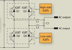
My problem is at Filter side below is my filter circuit and my questions

1-is filter circuit correct ?? if yes then what are the inductor and capacitor values ??
2-if the circuit is incorrect then what is the correct circuit ??? and what will be the exact values of capacitor and inductor ??
3-which side of the out put bridge is phase and neutral ? because input neutral will sink with out put neutral ???
1-load 800w
2-oscillator frequency is approx is 50khz
3-boost volt 315v dc
4-out put pure sine wave through h-bridge 220v ac at 50hz
My problem is at Filter side below is my filter circuit and my questions

1-is filter circuit correct ?? if yes then what are the inductor and capacitor values ??
2-if the circuit is incorrect then what is the correct circuit ??? and what will be the exact values of capacitor and inductor ??
3-which side of the out put bridge is phase and neutral ? because input neutral will sink with out put neutral ???
Last edited:


