Continue to Site

Welcome to EDAboard.com

Welcome to our site! EDAboard.com is an international Electronics Discussion Forum focused on EDA software, circuits, schematics, books, theory, papers, asic, pld, 8051, DSP, Network, RF, Analog Design, PCB, Service Manuals... and a whole lot more! To participate you need to register. Registration is free. Click here to register now.

Slew rate simulation of a discrete Op amp on Ltspice

PorDeseign00

Newbie level 5
Joined
Mar 13, 2024
Messages
9
Helped
0
Reputation
0
Reaction score
0
Trophy points
1
Activity points
65
Hello everyone.

I have a problem with the simulation of the slew rate of a two-stage op amp on Ltspice..

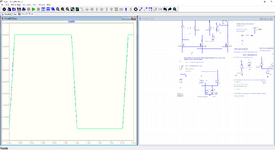
When I configure the op amp as a unity gain buffer the simulation goes into an infinite loop and I can't see the response speed of my op amp. when I connect the square wave pulse to one input terminal Vin+ of the op amp and connect the other to gnd without carrying out the feedback, I can measure the slew rate, but I don't think it's the right method.

Thank you so much!!

Slew Rate op amp.PNG
 
There must be a large imbalance in charge, Q for the M1, M2, M3, and M4 drivers to cause more asymmetry. It is more obvious with C2 removed. I could see no obvious way to balance it. It seems in the overdrive case, things become rather non-linear and unbalanced.
 
Last edited:
so having a charge imbalance there will be different charge/discharge switching times regarding capacities. Perfect, thank you very much! but if the currents are perfectly balanced at 30mA on the differential amplifier, how is it possible that there are unbalances? I'm thinking that they are due to the parasitic capacitances of the MOS in question...
 
It looks better in linear mode. GBW = 389 MHz = 100 * 0.35 / 90 ns , SR = 400mV/90 ns
1719764302803.png

--- Updated ---

Correction: The asymmetry seems to be a bug in LTspice with the duty cycle of 1us / 2us being wrong.
This is the VD1 = AC1 pulse gen. node PULSE(-2m 2m 0 0 0 1u 2u 10)

Or is it a bug in my understanding of LTSpice with 5% slopes added when 0 was specified?

where 0.91 / 2 us pulse comes out as 1.0 / 2.0 us
View attachment 191972

Why the asymmetry in the pulse gen?

1719768974440.png


1719769127743.png


Precompensated duty cycle
1719770179024.png
 

Attachments

  • ProveDiff_TS.zip
    4 KB · Views: 7
  • 1719767226930.png
    1719767226930.png
    143.3 KB · Views: 11
Last edited:
Discovery
After reading the .log file, LTspice automatically adds a rise time of about 10% a fixed number in ns whichever is smaller, presumable to prevent division by zero for currents. Thus the duty cycle will become asymmetrical for high-frequency square waves unless you realize how to create the ON time by adding 10% to the period = Trise_fall or something close to this. This makes it difficult to specify perfect 50% duty cycle Pulses >= 10 MHz.

PULSE({Vi} {Vf} {Tdelay} {Trise_fall} {Trise_fall} {Tperiod/2+Trise_fall} {Tperiod})

- where Trise_fall when specified to 0 will become ~ 10% of Tperiod for very short periods in ns or us.

In the previous example, I subtracted 15% of Tperiod to the value after Tf to obtain close to 50% from sig. gen.

Whereas, LTspice help says nothing about adding 10%Tperiod to Tr=0, Tf = 0.

"PULSE(V1 V2 Tdelay Trise Tfall Ton Tperiod Ncycles)"
 
Last edited:
Hello!!Is there a way to decrease the output impedance of this amplifier?? I noticed that it has an output impedance of about 990 ohms and I would like to reduce it. I know it is possible to use a buffer to match the impedance, but I would like to know if there are other methods as well. Thank you very much!!
 

LaTeX Commands Quick-Menu:

Part and Inventory Search

Welcome to EDABoard.com

Sponsor

Back
Top