Continue to Site

Welcome to EDAboard.com

Welcome to our site! EDAboard.com is an international Electronics Discussion Forum focused on EDA software, circuits, schematics, books, theory, papers, asic, pld, 8051, DSP, Network, RF, Analog Design, PCB, Service Manuals... and a whole lot more! To participate you need to register. Registration is free. Click here to register now.

Single conductor inside hollow conductor

Status
Not open for further replies.
50 Hz is way too low for 13 turns on an unknown core size

for ferrite Bpk < 0.3T Bpk = Erms /( 4.44 F. N Ae ) for sine wave. Ae = ferrite core area, N = turns, F = Hz

- - - Updated - - -

area in m^2
 
It makes sense to characterize the transformer in terms of mains and leakage inductance plus large signal parameters.

In case of 50 Hz application, leakage inductance can be effectively neglected, but main inductance respectively magnetizing current can't. The voltage drop you are seeing isn't caused by insufficient coupling but voltage drop due to magnetizing current. It would be roughly the same with regular transformer windings and same number of turns.
 
13 Turns on a steel core will give you a much better indication @ 50Hz
 

13 Turns on a steel core will give you a much better indication @ 50Hz

The core I used is hitachi amcc100. I mistakenly said that it was 13 turns on core. I initially had 6 turns on core and was seeing the lower voltage. When I went to 13 turns the coupling was much better. In both cases the current was higher when voltage was applied to outer conductor. My apologies for the misinformation. I work away from home 4 weeks at a time and trying to recall things from memory. When I get back home I will take measurements again and post them.
 

I applied 3 vac across center conductor and measured 1.4 vac on shield wire. When I applied 3 volts to shield wire I measure 2.71 volts on center conductor.

I do not have any direct explanation but these come to the mind:

1. The two conductors are not symmetrically places. Because the shield is floating, a large part of the electric field is blocked and a smaller part of the magnetic field is also blocked (more if the shield is solid). That I guess is the reason for case I. Correct way, in my opinion, is to twist two coaxes nicely, connect the shields to the ground (fixed voltage) and measure the effects between two core conductors. There are coaxes with foil shields and they may be used for more reliable results.

2. When the shield is used a primary, the electric field will be zero inside but the magnetic field will be not. But because of the gap (there will be some space), we shall have some leakage. Hence I expect higher voltage for case II.

You should carry out the experiment (i) without a core and (ii) with a simple rod (iron or ferrite) whose length is larger than the coil length.

3. By the way, did you measure the current?
 
if anyone wishes to continue he discussion of potential, emf and voltage, etc,
please start a new thread under physics
as this seems somewhat far afield from kajunbee's question
 

@cmitra I did measure input current, but I'm unable to say with certainty what it was. Will be another 5 days before I get back to house. I ordered a 16' roll of .026" Id soft copper capillary tubing and 23 gauge magnet wire. Hopefully I will be able to insert the wire in tubing. Since the copper tubing has no insulation do you think I could get away with using polyurethane spray varnish like used on furniture?
 

Since the copper tubing has no insulation do you think I could get away with using polyurethane spray varnish like used on furniture?

If the voltages are small enough, there should be no problem.

In my student days, I have seen electromagnets made with copper tubes covered with cotton threads and heavily varnished. Water mixed with glycol (I think) used to be circulated with a pump in a closed circuit which is in turn cooled with chilled water...

To thread the wire in the tube: ensure there is no blockage by first blowing air. Then pass some light oil (paraffin oil is very good) to reduce friction. Then try to push the magnet wire slowly. I should not be difficult. If you wish to remove the oil, use water mixed with some detergent and finally use alcohol and air to remove the last traces of alcohol.

Finally, do not use very high frequency to do the final experiment because copper will block high frequency magnetic field also. A low frequency, the skin depth is large and you can get useful results.
 
Proving to be more difficult than I expected. The 23 gauge will start but just the slightest bend in wire or tubing will cause it to jam up. I will try with 24 gauge and see how that goes. If that doesn't work I may go with larger capillary tubing. Basically insert the smaller tubing inside a larger tube. It should not be as difficult to insert solid wire through the larger Id tubing. I can then solder the wire into the smaller tubing. And then use wire to pull small tubing through larger tubing.
I'm trying to keep as tight as possible to minimize air gaps and keep inner conductor centered. But not sure if worth extra effort. How might these things effect the output?
 

After several attempts I was able to put something together. I was able to manage 40 turns on the same core I had used previously. The tubing ws .065" Id with 23 gauge wire inserted. These are a few measurements I took with tubing as primary.

Primary applied voltage- 2.28 vac amps - 1.98
Secondary voltage - 2.27 vac

Primary voltage - 3.96 vac amps - 2.31
Secondary voltage - 3.96 vac

Primary voltage - 4.94 vac amps - 2.63
Secondary - 4.93 vac
 

To pull wire through a tube, first use a vacuum cleaner to s-u-c-k a string through the tube. (It works quickly whether the tube is coiled or straight.) Tie the wire to the string, then pull on the string which in turn pulls the wire.
 

To pull wire through a tube, first use a vacuum cleaner to s-u-c-k a string through the tube. (It works quickly whether the tube is coiled or straight.) Tie the wire to the string, then pull on the string which in turn pulls the wire.

I did try the vacuum at one point but without success. I have done that before with larger conduit and it works really well. With larger conduit you can tie a cloth or foam ball to string to make a tighter seal. That would be very difficult with the small tubing I'm using. What I found made it easiest for me was to have the tubing as straight as possible. I learned a little trick to do this. I had someone hold one end with vise grip pliers while I held other end same way. Then strike the jaws of pliers with a hammer in same direction your pulling. With just a few light taps the tubing was almost perfectly straight.

- - - Updated - - -

The most unique way I have seen someone fish a string is with a blowgun. And electrician I knew years ago would use a 1/2" conduit to shoot a dart with string attached across the top of acoustic drop ceilings.
 
so you have made a 1:1 transformer - well done ...!

But a very poor one it seems. I took some measurements with a 5.1 ohm resistor as load.

Applied voltage primary - 3.27 volts @ 2.66 amps
Secondary voltage - 3 volts @ .588 amps

I'm not very skilled when it comes to oscilloscope measurements. But from what I can tell there is a phase shift of approximately 45 degrees measured at secondary. But I was under the impression there would be no phase shift with a resistive load. I am using a CT for measurements. Is this expected.

- - - Updated - - -

The phase shift is current leading.
 

If the measurements are correct, a large share of the primary current runs as magnetizing current into the transformer inductance. You only told about AMCC-100 core (an amorphous cut tape) but nothing about the geometry (cross section, magnetic path length, any air gap?).
 
If the measurements are correct, a large share of the primary current runs as magnetizing current into the transformer inductance. You only told about AMCC-100 core (an amorphous cut tape) but nothing about the geometry (cross section, magnetic path length, any air gap?).
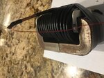
IMG_4519.jpgIMG_4521.jpgIMG_4518.PNGIMG_4517.PNG

- - - Updated - - -

I found and isolation transformer so now I am able to see waveform on primary. It is opposite of secondary, current lagging. But current is leading in secondary.

- - - Updated - - -

The varnish didn't work so I had to wrap tubing with electrical tape.
 

Applied voltage primary - 3.27 volts @ 2.66 amps
Secondary voltage - 3 volts @ .588 amps

I presume these are RMS values. I agree with what FvM says (#35) but it may not be a bad thing considering the simple design principles.

But I have forgotten the original question (I was away for over a week) but also try with the primary and secondary interchanged.

ALso estimate the power factor. In this particular geometry you are using, the role of the core will be much less. As you have a U-U core, try putting some gaps using thin sheets of plastic (of known thickness).

By the way, oscilloscope measurements are not difficult but the number of buttons can be scary!

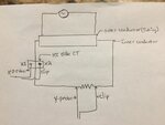
The reason I included probe placement in diagram was because there seemed to be a polarity to follow. If I reversed one probe the angle was much greater and flipped if I'm not mistaken. So I'm not really sure which way was correct. I probably should asked this question first, but how do you tell which way is correct.
 

but how do you tell which way is correct.

There is no way to ensure that the CT is not introducing any phase shift. So if you want to measure the phase of the current, you should not use the current transformer at all...

By the way, phase is a relative concept; you should measure the phase of the voltage or current in the secondary with respect to the phase in the primary.

In this particular case the load is a resistor and the current and voltage are expected to be in phase. Do you suggest that the current and voltage in the resistor (that is acting as a load) are NOT in phase?

Do a simple simulation with software and see the result.
 
Status
Not open for further replies.

Part and Inventory Search

Welcome to EDABoard.com

Sponsor

Back
Top