Continue to Site

Welcome to EDAboard.com

Welcome to our site! EDAboard.com is an international Electronics Discussion Forum focused on EDA software, circuits, schematics, books, theory, papers, asic, pld, 8051, DSP, Network, RF, Analog Design, PCB, Service Manuals... and a whole lot more! To participate you need to register. Registration is free. Click here to register now.

sine wave oscillator

Status
Not open for further replies.
Hi Crutschow - one question: Did you also try to place the anti-parallel diodes across R2 only?
According to my experience, this should work better to keep the amplitude constant.
I did try simulating that and the amplitude variation over the frequency range was much higher (from about 0.6Vpk to 1Vpk).
 

Just read the 8038 documents dude. Refine your practical implementation based on their recommendations. Do a bit of work on careful following of their advice. Shortcuts don't work when you want < 1% accuracy. You'll get the desired results.

In addition, I am really interested to know how you determined that the distortion was 'higher' than what you wanted. How DID you measure it ?
 

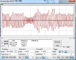
Thx crustschow. I tried simulating the circuit with Multisims using the same components, the output seems to continuously vary both in frequency and in amplitude as in the fig attached. You got the same thing? and did u build the circuit in hardware? out1.jpg

- - - Updated - - -

Hi Crutschow - one question: Did you also try to place the anti-parallel diodes across R2 only?
According to my experience, this should work better to keep the amplitude constant.

Right! i tried it on Multisims and removed both diodes, the output was much better amplitude wise. I replaced R5 with a pot and got variable frequency output. I think I will implement the circuit now.
Thanks
 

Status
Not open for further replies.

Similar threads

Part and Inventory Search

Welcome to EDABoard.com

Sponsor

Back
Top