liteon
Full Member level 2

- Joined
- Oct 13, 2010
- Messages
- 149
- Helped
- 27
- Reputation
- 54
- Reaction score
- 27
- Trophy points
- 1,308
- Location
- PAKISTAN
- Activity points
- 2,510
I agree! Mr. Hameed this is such a great work which I was looking for! THANK YOU! I downloaded the RAR files, I could open the proteus circuit and simulate but I want to view the C code. Only the hex code appears. How may I do this correctly? I'd appreciate if you could hep me!
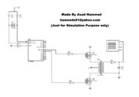
By the way, I watched your video about this project on youtube and I guess I saw three mosfets. In the proteus there are only two of them. Why did u use the third one in your application on the video? Another thing is that it's said that the output is 220 Volts but in proteus circuit according to oscilloscope it appears that the output is 40 mVolts. Could you please explain this?
I wish you and everyone good working!
No there are two Mosfets at the transformer driver board.The third at the board with the pic16f84a is the 5 volts regulator to power the pic16f84a.
The output is around 230v without a load at transformer.And i dont know much about the proteus but i think 40mv is the division for signal measurement at the oscilloscope.
may be someone else could explain it better.


