Continue to Site

Welcome to EDAboard.com

Welcome to our site! EDAboard.com is an international Electronics Discussion Forum focused on EDA software, circuits, schematics, books, theory, papers, asic, pld, 8051, DSP, Network, RF, Analog Design, PCB, Service Manuals... and a whole lot more! To participate you need to register. Registration is free. Click here to register now.

Sine Wave Inverter Design Help

Status
Not open for further replies.
This is regarding 12V to 230V Output transformer based Push-Pull Inverter.

Here in this link

https://www.instructables.com/id/250-to-5000-watts-PWM-DCAC-220V-Power-Inverter/

he mentions

For every 1amp of 220vAC you will be draining like 8 to 10 Amps from the 12v battery, make your calculations

So, If I design a 500VA or 500W Inverter then Output current (230V side) will be I = P/V = 500W/230V = 2.174A

So, approx 21.74A current is drawn from the 12V battery.

So, I can safely use ACS712-30A to monitor the battery current in Inverter mode and also while battery is charging. Right ?

because during full load 22A will be flowing in the battery circuit and during battery charging 10 to 14A current will be flowing.

Right now, I have ordered one 12-0-12V to 230V 500VA transformer for Inverter and another 230V to 12V 10A step down transformer for battery charging.

I have also ordered Rigol 1054Z Oscilloscope. I will get them in 4 weeks.

I will build the Inverter and post all voltages, currents and signals data here.
 

Is this circuit ok for Feedback Circuit. 230V AC Inverter Output is scaled to 2.5V DC for adc input. Based on this feedback value PWM duty is adjusted to obtain constant output voltage of 230V AC.

In Proteus I am not getting exact and stable 2.5V DC.
 

Attachments

  • FB Circuit.png
    FB Circuit.png
    22.5 KB · Views: 144
  • Feedback Circuit.rar
    25 KB · Views: 141

For a 500W Inverter (DC-DC Converter Based)

I = P / V = 500W / 230V = 2.174A

Transformer Calculations

Half-Bridge forward Converter is used.

So, the transformer primary needs a center tap.

Ref: https://tahmidmc.blogspot.in/2012/12/ferrite-transformer-turns-calculation.html

Npri = (12 * 10^8) / (4 * 100000 * 1500* 1.25) =

Npri = 1.6 turns

Taking it as 2 turns

We get 2 + 2 turns for the primary

N = Vsec:Vpri = 330V:10.29V = 32.06

Nsec = N * Npri = 32.06 * 2 = 64.12

taking it as 64 turns

Current Calculation

Ref: https://www.electrical4u.com/design-of-high-frequency-pulse-transformer/

Imax = 2.174A and this is the current that flows through the Mosfets and also through the secondary of the switching transformer.

Ipri = (Nsec/Npri) * Isec

Ipri = (64 / 2) * 2.174A = 69.568 = approx 70A

Ref: https://www.powerstream.com/Wire_Size.htm

https://www.engineeringtoolbox.com/wire-gauges-d_419.html

Copper AWG for Primary is (taking Pri current as 100A) 4 AWG

Copper AWG for Secondary is (taking Sec current as 5A) 22

A 12V 140Ah Battery is used

Battery Backup Time Calculation

On full load

Ref: **broken link removed**

UPS Backup [in hours] = Battery Ah * Volts/(Load/Power Factor)

UPS Backup [in hours] = 140 Ah * 12 / (500W / 1.0) = 3.36

The calcuator here

https://www.backupbatterypower.com/pages/ups-run-time-calculator

is giving 3:21:36 with 500, 1, 1, 12, 140 datas

Are these calculations correct. Please answer.
 

@BradTheRad

Can you explain how you calculated low side or primary current here in post #2 ?

https://www.edaboard.com/threads/224066/

Show the current calculation for 12-0-12V to 230V step-up Inverter transformer. Inverter is 500W.

I could not understand the method you used for primary current calculation. Upto 800VA Inverters 12V Single Battery is used and a 12-0-12V to 230V transformer will be used with push-pull topology.

So, only 12V gets applied to half of the primary winding at a time.

So, Ipri = 500W / 12V = 41.67A ?

I calculated this way

Isec = Pout/Vout = 500W/230V = 2.174A

Ipri = Vsec/Vpri * Isec

Ipri = (230/12) * 2.174A = 41.668A

Please tell me whu you took 24V for 500VA Inverter's transformer's primary current calculation.
 

You cannot get 12v rms from only a 12v battery to drive the primary.
Best you can hope for is 12v peak from a 12v battery, in practice something a bit less than that due to mosfet and wiring voltage drops.

A 12v battery can only produce slightly less than 8.45v rms, so your 230v secondary will have something like 162.6 volts rms, far short of 230v.

And also remember, a 12v (nominal) battery may see a terminal voltage of anything from about 10.0 volts to 14.0 volts, depending on the circumstances.

**************update**************

A 500Va transformer is a large expensive beast, and all is not lost.
If it's toroidal and has two 12v windings, as seems to be the norm these days, the dual secondaries are usually wound on top.

You could start off by just experimentally removing a few turns from each of the secondary windings to reach the required output voltage.

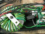
A better way would be to totally remove the existing 12v primaries, and wind your own using pvc covered building wire. It sounds pretty dramatic, but its actually pretty easy. And you can fiddle the number of turns pretty easily.
You may then end up with something that looks something like this :

transformer.JPG

The home brew inverter guys do this all the time and its a well proven method.
 
Last edited:
  • Like
Reactions: Okada

    Okada

    Points: 2
    Helpful Answer Positive Rating
Then how are the 12V single battery 230V 50Hz Inverters are designed ? I see many of them for 150W to 800W Inverters they use single 12V battery with different Ah ratings.

These are the new calculations. Previous calculations had some errors.


For Bulky Output Transformer Based Inverter

Input Voltage 12V DC
Output Voltage 230V AC 50Hz
SPWM frequency 12 KHz
Inverter Power = 500W

Battery = 12V 200Ah

I = P / V = 500W / 230V = 2.174A

---------------------------------------------------------------------------------------------------------------

Current Calculations

Isec = 2.174A

Ipri = (Vsec/Vpri) * Isec

Ipri = (230/12) * 2.174A = 41.6683A

N = Vsec/Vpri = 230V/12V = 19.167

If Npri = 50 turns then

Nsec = N * Npri = 19.167 * 50 = 958.35 turns = approx 958 turns

--------------------------------------------------------------------------------------------------------------
Wire Guages

Ref: https://www.powerstream.com/Wire_Size.htm

https://www.engineeringtoolbox.com/wire-gauges-d_419.html

Copper AWG for Primary is (taking Pri current as 52A) 10 AWG = 2.59 mm dia, 5.26 mm^2

Copper AWG for Secondary is (taking Sec current as 5A) 22 AWG = 0.64 mm dia, 0.33 mm^2

--------------------------------------------------------------------------------------------------------------
A 12V 200Ah Battery is used

Battery Backup Time Calculation

On full load

Ref: **broken link removed**

UPS Backup [in hours] = Battery Ah * Volts/(Load/Power Factor)

UPS Backup [in hours] = 200 Ah * 12 / (500W / 1.0) = 4.8 hours

-----------------------------------------------------------------------------------------------

On full load 42A current have to flow through Mosfets and primary side of transformer

Mosfet is FDP8440, Rds(on) at Vgs = 10V is 1.64 mOhms

Pd(mosfet) = Id^2 * Rds(on) = 42 * 42 * 0.00164 = 2.893W = approx 3W

This is kept cool using a 12V DC Fan.

On full load 3W is dissipated but Inverter will never run at full load.

Load max will be 300W

So, Imax = 300/230 = 1.304A

Ipri = N * Isec = 19.167 * 1.304A = 25A

Pd = 25 * 25 * 0.00164 = 1.025W

--------------------------------------------------------------------------------------------

For Battery Charger a 230V to 12V 300VA step down transformer is used

I = 300/12 = 25A

Battery = 12V 200Ah

Charging Current will be 20A

So, transformer can provide 20A

Mosfet is used with PWM to control charging current

Pd(charger mosfet) = 20A * 20A * 0.00164 Ohms = 0.656W

---------------------------------------------------------------------------------------------


2 x VS-HFA15TB60PbF diodes are used in charger circuit

10A flows through each diode

Vf @ 15A is 1.3V

Pd(diode) = VI = 1.3 * 10 = 13W

Show me a ultrafast soft recovery diode 15A or higher with low Vf.

Can I use 1x DUR6040WT ?
---------------------------------------------------------------------------------------------
PCB track width calculations

Ref: https://www.4pcb.com/trace-width-calculator.html

Thickness 2 oz/ft^2

For Output side i.e., 230V 5A side

3.6 mm

For input side i.e., 42A side

67.7 mm

----------------------------------------------------------------------------------------------

Total Power loss assuming transformer power loss to be 2W

P(loss total) = Pd(mosfets) + Pd(diodes) + pd(transformer)

= 3W + 26W +2W = 31W

----------------------------------------------------------------------------------------------------

How to calculate efficiency ?

What is Pinput ?

Battery Voltage * Battery Current(@ particular load) ?

Pinput = 12V * 42A = 504W ?

Poutput = Pinput - Ploss ?

= 504W - 31W = 473W ?

------------------------------------------------------------------------------------------------------


Calculation of current if efficiency is 86%

Ipri = 42A @ full load

42A/0.85 = 49.4A

-------------------------------------------------------------------------------------------------------

- - - Updated - - -

Edit:

I made a mistake in power calculation.

Battery Charging Circuit diodes power loss is not counted in efficiency because it is power loss during mains presence.

So, only mosfet power loass and transformer power loss in considered for Inverter.

So, in my Inverter for full load 3W + 2W = 5W is the power loss.
 

First thing you do is decide what the minimum battery voltage is going to be to reach a full 230v. Suppose we choose 10.0 v as our minimum.

The most our PWM can ever achieve across the primary will be 10.0 volts.
So we decide 10.0v will be peak, and 7.071 volts will be rms.

To reach 230v rms in the secondary, we require a 7.0 volt to 230 volt transformer.
That is a ratio of close to 33:1

If our secondary power is 500 watts, at 230v, our secondary current will be 2.17 amps just as you say.
Primary current will be roughly 33 times that or 71.7 amps rms.

But our mosfets also reach peak primary current of 1.414 times that or about 101 amps peak.
 
  • Like
Reactions: Okada

    Okada

    Points: 2
    Helpful Answer Positive Rating
Ok. it is clear now. I will make new calculations.


Can I use the same 12-0-12V to 230V step-up Inverter transformer for battery charging also ?

Transformer is designed to handle 120A primary current and 5A secondary current in Inverter mode.

In battery charging mode the windings gets reversed

So, I will be supplying 230V 5A max to the primary side

In 12-0-12V secondary side only 12-0V is used for battery charging.

As Inverter mode primary winding can handle 120A it will not be a problem to conduct 20A battery charging current ?

Ipri = (vsec/Vpri) * Isec

Isec = 20A

Ipri(rms) = (12V/230V) * 20A = 1.043A rms

So, 5A winding side can easily handle this 1.043A input current

After bridge (GBPC3510) taking 1.1V drop across each diode so total 12V rms gets converted to
Vpk of 12 * 1.414 - 2.2V = 14.77V

Is this voltage sufficient for Battery charging ?

I need to charge 12V 200Ah Battery.

I will use additional relays to switch the transformer between Inverter mode and battery charger mode.
 
Last edited:

If you are using push pull, the inverter transformer will need to have two seven volt windings with a centre tap.

For battery charging you may be able to use the exact same fourteen volt winding with a bridge rectifier.
 
  • Like
Reactions: Okada

    Okada

    Points: 2
    Helpful Answer Positive Rating
Show the current calculation for 12-0-12V to 230V step-up Inverter transformer. Inverter is 500W.

I could not understand the method you used for primary current calculation. Upto 800VA Inverters 12V Single Battery is used and a 12-0-12V to 230V transformer will be used with push-pull topology.

So, only 12V gets applied to half of the primary winding at a time.

So, Ipri = 500W / 12V = 41.67A ?

I calculated this way

Isec = Pout/Vout = 500W/230V = 2.174A

Ipri = Vsec/Vpri * Isec

Ipri = (230/12) * 2.174A = 41.668A

Please tell me whu you took 24V for 500VA Inverter's transformer's primary current calculation.

In the push-pull design, the input is centre tapped and each half carries current alternately. Therefore one half of the primary is cooling off.

In this case, you can use a thinner wire because the average current comes to about 1/2 of what you calculated.

You can get the same result if you assume the primary is 24V and current is 20.xy amps. The same equation: Vpri*Ipri=Vsec*Isec >>> all the power is transferred to the other winding and there is no loss in this transfer
 
  • Like
Reactions: Okada

    Okada

    Points: 2
    Helpful Answer Positive Rating
If you are using push pull, the inverter transformer will need to have two seven volt windings with a centre tap.

For battery charging you may be able to use the exact same fourteen volt winding with a bridge rectifier.

In Battery Charging mode. 230V is applied to secondary side and low voltage is obtained from primary side. Why do you say that even in battery charging mode the tarnsformer peimary side doesn't give 12-0-12V but gives 7-0-7V ? What is the reason for it ?

I am not building transformer. I am going to use readily available 12-0-12V to 230V 500VA Inverter Transformer.

I am buying from here.

**broken link removed**

See that attached PDFs. Proteus files are also included. Which is better ? using 12-0V winding or 12-0-12V winding without center tap for battery charging ?

I have another problem. RL2 relay is used to switch the transformer winding between mosfets and bridge rectifier. In battery charging mode 20A current flows and if I use 30A contact type relay then it can handle the 20A but what about the current flowing during Inverter mode. You say that 100+A current flows through Mosfets. How to handle this much current in relay ? I was not able to find relay with more than 30A contact rating.

Also ACS712 cannot be used for measuring current flowing through mosfets. Should I go with a C.T for measuring current through Mosfets in Inverter mode ?
 

Attachments

  • Proteus Files.rar
    73.5 KB · Views: 131
  • PSWI RevB.PDF
    49.3 KB · Views: 156
  • PSWI RevC.PDF
    50.3 KB · Views: 135

Status
Not open for further replies.

Similar threads

Part and Inventory Search

Welcome to EDABoard.com

Sponsor

Back
Top