Continue to Site

Welcome to EDAboard.com

Welcome to our site! EDAboard.com is an international Electronics Discussion Forum focused on EDA software, circuits, schematics, books, theory, papers, asic, pld, 8051, DSP, Network, RF, Analog Design, PCB, Service Manuals... and a whole lot more! To participate you need to register. Registration is free. Click here to register now.

Sine wave constant current amplifier

Status
Not open for further replies.
It may be straightforward but not necessary simple or easily made stable with an inductive load. Since he stated that a square-wave would be okay, I showed a simple circuit that generates a current limited output and is stable with an arbitrary inductive load.
Maybe I'm relying too much on the original specification that talks about DDS and 1 A sinoidal current.

I think that the stability problems can be easily overcome, but yes a certain analog design knowledge will be required.

Instead of feedback, current control through software might be an option, requiring a current measurement however.

A discrete transistor driver isn't bad as such. I would prefer internal feedback per stage instead of being stuck to transistor current gain variations and nonlinearity.
 

....................................

A discrete transistor driver isn't bad as such. I would prefer internal feedback per stage instead of being stuck to transistor current gain variations and nonlinearity.
The circuit I posted uses 100% emitter feedback so is relatively insensitive to transistor gain variations and nonlinearities.
 

The circuit I posted uses 100% emitter feedback.
As shown, I would describe the circuit as switched resistor source. Hardly better then a push-pull dríver with 5 ohm series resistor. To make the emitter feedback work as a current source, there must be a lower voltage drop, e.g. 1V across the resistor and a respectively modified base control circuit.
 

But you can imagine a shunt resistor (say 1 ohm) to sense the current?

I am already taking the line back to negative input. What would an extra 1 ohm resistor do?

There should be someone like a supervisor to help with the prerequisites of your software work. (Hopefully it's not over his head as well)

This is for my hobby at home so there are no electronics engineers.
As for the supervisor for the software - at my level I am the supervisor.

- - - Updated - - -

Maybe I'm relying too much on the original specification that talks about DDS and 1 A sinoidal current.

I think that the stability problems can be easily overcome, but yes a certain analog design knowledge will be required.

Instead of feedback, current control through software might be an option, requiring a current measurement however.

A discrete transistor driver isn't bad as such. I would prefer internal feedback per stage instead of being stuck to transistor current gain variations and nonlinearity.

Basically, a "complete" device would have a software controlled DDS that then drives a coil with 1A current having the single frequency sine wave output from the DDS. Ideally, circuit should support reasonably varying coil resistances and inductance.
As an add on, being able to control current from 1A to more would also be nice, but...Having a sine wave I would have a single frequency. With square wave, I get multiple frequencies in my signal.
Power supply would be ATX power supply that can give +12,-12,+5,-5 and 3.3V with high amps, so I can power amplifiers and control logic with it. And power supplies are easily obtainable.
Sine wave frequencies would be usually in the 1-10kHz range and for special case about 50kHz may be needed.

However, at this point having a circuit as described above is fairly complex without doing any testing of the concept first.
That is why I if I have a super-simple circuit that can drive the coil and I want to see the output of the AC magnetic field being changed as being passed various near metal objects. Magnetic field will be measured with a sensitive 3-axis magnetometer IC (MAG3110 chip).I did some FEM analysis of the coil with N turns with 1A current of various diameters, and there I can see that the stuff should work.
When I have this concept proven, then design of a circuit with whole features will be next step where I can control sine frequency to be exact and not square wave.
 

I am already taking the line back to negative input. What would an extra 1 ohm resistor do?
Feedback is now from amplifier output, keeping the the coil voltage constant. Instead feedback can be made from a shunt resistor, keeping the voltage across the resistor respectively the coil current constant.
 

Feedback is now from amplifier output, keeping the the coil voltage constant. Instead feedback can be made from a shunt resistor, keeping the voltage across the resistor respectively the coil current constant.

So I connect coil and resistor in series and then after the resistor I take back the feedback back to opamp?

+V ---------- coil ------ resistor ------- fdbck wire --------- GND

Or I connect coil and resistor in parallel and take after the resistor feedback back:

+V --------+---- coil ---------+------- GND
| |
+ -resistor-fdbck - +


My guess is for coil and resistor to be in parallel and feeback is taken on the resistor branch after the resistor back to opamp.


EDIT:

And what would be the changes required to actually get sine-looking current out on the coil? Bcz in this one we are discussing simulation shows square wave looking current at correct frequency; and one with 4 transistors also.
 
Last edited:

For example I made a schematics and simulated it in TINA for the 5kHz sine wave oscillator (wien oscillator).
First opamp is the oscillator and then I did amplification so signal is nice with no clipping.
Now, if I can convert this into sine wave current regulated to 1A :)

Schematics is here:

5kHz-SineWave.png

I also did one for 5kHz square wave that can trigger the circuit with transistors only and 5ohm resistor. But no reason to post it here - it is simle multivibrator using 1 opamp.
 

As shown, I would describe the circuit as switched resistor source. Hardly better then a push-pull dríver with 5 ohm series resistor. To make the emitter feedback work as a current source, there must be a lower voltage drop, e.g. 1V across the resistor and a respectively modified base control circuit.
Your are correct. My brain was in neutral. :-| Scratch my circuit as shown.
 

Okay, here's a feedback circuit that generates a constant current AC output signal. I used a high frequency current-mode op amp to eliminate output oscillations and minimize crossover distortion. Standard voltage-feedback op amps tend to generate output oscillations with the inductive load.

The frequency is limited to about 7kHz with a 250µH load due to the output voltage limitation (about ±12V) of the op amp. It will go to 20kHz with a 100µH load.

I used transistors available in my simulation library but you can use just about any BJT's rated for >40V and >1A.

Edit: If the small oscillations noted on the output voltage (but not showing in the output current) are a problem than a compensation capacitor of about 1nF across R1 should help.

Constant Current.gif
 
Last edited:

If the small oscillations noted on the output voltage (but not showing in the output current) are a problem than a compensation capacitor of about 1nF across R1 should help.

Stability is challenged by L1/R2 pole in the feedback loop. Alternatively to a compensation capcitor parallel to R1 (it works because LT1223 is CFB OP type), I would try a RC series circuit from amplifier output to inverting amplifier input that bypasses the inductor pole at high frequencies near loop unity gain bandwith.
 

Thanks all.

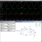
I will try to make the circuit based on post #29 and sine wave oscillator:

schem-sine-with-driver.png

Will report back the results.
 

One more thing - it seems my transistors are heating a lot.
Is there some good solution to limit the heating except adding a heatsink?
 

Losses are expectable for a linear output stage. You can reduce the output stage power supply to the minimum required for undistorted operation.
 

As you might need your available PSU Voltages when the output frequency rises and the Impedance of your load also increases such that increased voltage is needed for your 1 Amp current, would suggest using some heatsinking for your output transistors.
Small PCB type heatsinks without mounting insulation, but insulated otherwise, should be suitable as you will probably will have only about 3/2 Watts maximum dissipation for each device

Certainly, look at reducing Vs for your Output Stage should you still be below the initial design voltage when you have a working circuit.

hope this assists
Mik
 

Status
Not open for further replies.

Part and Inventory Search

Welcome to EDABoard.com

Sponsor

Back
Top