Continue to Site

Welcome to EDAboard.com

Welcome to our site! EDAboard.com is an international Electronics Discussion Forum focused on EDA software, circuits, schematics, books, theory, papers, asic, pld, 8051, DSP, Network, RF, Analog Design, PCB, Service Manuals... and a whole lot more! To participate you need to register. Registration is free. Click here to register now.

[SOLVED] Simulating Semi-floating gate current mirror using HSPICE

Status
Not open for further replies.
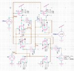
ULVinvcmCKT.JPG This is the schematic for the circuit. I have changed the typo error, but still I am not getting proper result.
Code:
* ULV Inverting current mirror recharge freq 25MHz

********* Simulation Settings - General section *********
.include "D:\HSPICE\NewCSFGBkup\t96w_9sf_9m_lb_3-params.txt"
.param vdd=450m v0='vdd/3.6' va='vdd/3.6' freq=8MEG delay=0 theta=0 phase=0

********* Simulation Settings - Parameters and SPICE Options *********

*-------- Devices: SPICE.ORDER > 0 --------
CCinn1 Vin N_3  .0002p   
CCinn2 Vin N_4  1p  
CCinp1 N_7 N_6  1p  
CCinp2 Vout N_2  .0002p 
MN_3 N_4 Vdd1 Gnd Gnd CMOSN W=2.5u L=250n AS=2.25p PS=6.8u AD=2.25p PD=6.8u  
MN_4 N_6 Vdd1 Gnd Gnd CMOSN W=2.5u L=250n AS=2.25p PS=6.8u AD=2.25p PD=6.8u  
MQ1 Vin N_3 Vdd1 Gnd CMOSN W=2.5u L=250n AS=2.25p PS=6.8u AD=2.25p PD=6.8u  
MQ4 Vout N_2 Vdd1 Gnd CMOSN W=2.5u L=250n AS=2.25p PS=6.8u AD=2.25p PD=6.8u  
MQ2 Vout N_4 Vdd2 Vdd CMOSP W=2.5u L=250n AS=2.25p PS=6.8u AD=2.25p PD=6.8u  
MQ3 Vin N_6 Vdd2 Vdd CMOSP W=2.5u L=250n AS=2.25p PS=6.8u AD=2.25p PD=6.8u  
MP_1 N_2 Vdd2 Vdd Vdd CMOSP W=2.5u L=250n AS=2.25p PS=6.8u AD=2.25p PD=6.8u  
MP_2 N_3 Vdd2 Vdd Vdd CMOSP W=2.5u L=250n AS=2.25p PS=6.8u AD=2.25p PD=6.8u  
VVsupply Vdd Gnd  DC vdd 
VVf Vdd1 Gnd  PULSE(0 vdd 0 2.5n 2.5n 15n 40n)  
VVfbar Vdd2 Gnd  PULSE(0 vdd 20n 2.5n 2.5n 15n 40n)  

VVa N_7 Gnd SIN(v0 va freq delay theta phase) $sinusoidal sweep


********* Simulation Settings - Analysis section *********
.tran 40n 1u

.print tran ID(MQ1)
.print tran ID(MQ2)

.meas maxIn MAX I(MQ1) from=900ns to=997ns
.meas maxIout MAX I(MQ2)  from=900ns to=997ns

********* Simulation Settings - Additional SPICE commands *********

.end

But when I keep all capacitors as 1pF and keep clock pulse height as 1V I am getting this output Capture.JPG
 

... when I keep all capacitors as 1pF and keep clock pulse height as 1V I am getting this output

You had 200aF before, which is much too low. Try with 200fF ! I think you should first come closer to the paper's suggestion. Here's your changed SPICE file, I'd suggest to try. More comments below.

Code:
* ULV Inverting current mirror recharge freq 25MHz

********* Simulation Settings - General section *********
.include "D:\HSPICE\NewCSFGBkup\t96w_9sf_9m_lb_3-params.txt"
.param vdd=[B]250m[/B] v0=[B]'vdd/2'[/B] va='vdd/2' freq=2MEG delay=0 theta=0 phase=0

********* Simulation Settings - Parameters and SPICE Options *********

*-------- Devices: SPICE.ORDER > 0 --------
CCinn1 Vin N_3   [B].2p[/B]   
CCinn2 Vin N_4  1p  
[B]*[/B]CCinp1 N_7 N_6  1p  
CCinp2 Vout N_2  [B].2p[/B] 
MN_3 N_4 Vdd1 Gnd Gnd CMOSN [B]W=250n[/B] L=250n  
MN_4 N_6 Vdd1 Gnd Gnd CMOSN [B]W=250n[/B] L=250n  
MQ1 Vin N_3  Vdd1  Gnd CMOSN [B]W=250n[/B] L=250n  
MQ4 Vout N_2 Vdd1 Gnd CMOSN [B]W=250n[/B] L=250n  
MQ2 Vout N_4 Vdd2 Vdd CMOSP [B]W=250n[/B] L=250n  
MQ3 Vin N_6  Vdd2  Vdd CMOSP [B]W=250n[/B] L=250n  
MP_1 N_2 Vdd2 Vdd Vdd CMOSP [B]W=250n[/B] L=250n 
MP_2 N_3 Vdd2 Vdd Vdd CMOSP [B]W=250n[/B] L=250n  
VVsupply Vdd Gnd  DC vdd
[B]VVgnd    Gnd  0   DC  0 [/B]
VVf      Vdd1 Gnd  PULSE(0 vdd   0  2.5n 2.5n 15n 40n)  * 25MHz
VVfbar Vdd2 Gnd  PULSE(0 vdd 20n 2.5n 2.5n 15n 40n)  

VVa [B]N_6[/B] Gnd SIN(v0 va freq delay theta phase) $sinusoidal sweep


********* Simulation Settings - Analysis section *********
.tran [B]1n[/B] 1u
.print tran ID(MQ1)
.print tran ID(MQ2)

[B]*[/B].meas maxIn    MAX I(MQ1) from=995ns to=1000ns
[B]*[/B].meas maxIout MAX I(MQ2) from=995ns to=1000ns


********* Simulation Settings - Additional SPICE commands *********
.end

1. Use the same low VDD voltage, in order to operate the MOSFETs in deep weak inversion (low currents!)
2. Use offset=amplitude for the sinus input
3. Dismiss Cinp1 (s. 6. below)
4. Use min. width transistors (s. paper). The (new) AS, PS, AD, PD values will be calculated by HSPICE
5. Use the Vgnd source
6. Couple the sinusoidal source directly to N_6. The DC offset of the sinus source can't surmount Cinp1
7. For the transient simulation use a lower step value for better resolution
8. The .meas statements don't make sense for the sinusoidal sweep. You have to compare the mirror currents Iin & Iout directly for the whole sinusoidal input.

Hope this helps!
 

Hi erikl, I used the code you gave and the output is like this Capture1.JPG
Then I tried this code, I used VDD as 450mV because I am using the same model file I posted before which has VTH0 of NMOS and PMOS equal to 450mV
Code:
* ULV Inverting current mirror recharge freq 25MHz

********* Simulation Settings - General section *********
.include "D:\HSPICE\NewCSFGBkup\t96w_9sf_9m_lb_3-params.txt"
.param vdd=450m v0='vdd/3.6' va='vdd/3.6' freq=2MEG delay=0 theta=0 phase=0

********* Simulation Settings - Parameters and SPICE Options *********

*-------- Devices: SPICE.ORDER > 0 --------
CCinn1 Vin N_3  .002p   
CCinn2 Vin N_4  .002p  
CCinp1 N_7 N_6  1p  
CCinp2 Vout N_2 1p 
MN_3 N_4 Vdd1 Gnd Gnd CMOSN W=2.5u L=250n AS=2.25p PS=6.8u AD=2.25p PD=6.8u  
MN_4 N_6 Vdd1 Gnd Gnd CMOSN W=2.5u L=250n AS=2.25p PS=6.8u AD=2.25p PD=6.8u  
MQ1 Vin N_3 Vdd1 Gnd CMOSN W=2.5u L=250n AS=2.25p PS=6.8u AD=2.25p PD=6.8u  
MQ4 Vout N_2 Vdd1 Gnd CMOSN W=2.5u L=250n AS=2.25p PS=6.8u AD=2.25p PD=6.8u  
MQ2 Vout N_4 Vdd2 Vdd CMOSP W=2.5u L=250n AS=2.25p PS=6.8u AD=2.25p PD=6.8u  
MQ3 Vin N_6 Vdd2 Vdd CMOSP W=2.5u L=250n AS=2.25p PS=6.8u AD=2.25p PD=6.8u  
MP_1 N_2 Vdd2 Vdd Vdd CMOSP W=2.5u L=250n AS=2.25p PS=6.8u AD=2.25p PD=6.8u  
MP_2 N_3 Vdd2 Vdd Vdd CMOSP W=2.5u L=250n AS=2.25p PS=6.8u AD=2.25p PD=6.8u  
VVsupply Vdd Gnd  DC vdd 
VGnd Gnd 0 DC 0
VVf Vdd1 Gnd  PULSE(0 vdd 0 2.5n 2.5n 15n 40n)  
VVfbar Vdd2 Gnd  PULSE(0 vdd 20n 2.5n 2.5n 15n 40n)  
VVa N_7 Gnd SIN(v0 va freq delay theta phase) $sinusoidal sweep

********* Simulation Settings - Analysis section *********
.tran 1n 1u

.print tran ID(MQ1)
.print tran ID(MQ2)

********* Simulation Settings - Additional SPICE commands *********
.end
and got the output like this HS-ULVinvcm.JPG
When I did a parameter sweep in transient analysis using this code
Code:
* ULV Inverting current mirror recharge freq 25MHz
* CCinp1 shorted for comparision graph

********* Simulation Settings - General section *********
.include "D:\HSPICE\NewCSFGBkup\t96w_9sf_9m_lb_3-params.txt"
.param vdd=250m v0='vdd/3.6' va='vdd/3.6' freq=2MEG delay=0 theta=0 phase=0

********* Simulation Settings - Parameters and SPICE Options *********

*-------- Devices: SPICE.ORDER > 0 --------
CCinn1 Vin N_3  .002p   
CCinn2 Vin N_4  .002p  
*CCinp1 N_7 N_6  1p  
CCinp2 Vout N_2 .002p 
MN_3 N_4 Vdd1 Gnd Gnd CMOSN W=2.5u L=250n   
MN_4 N_6 Vdd1 Gnd Gnd CMOSN W=2.5u L=250n 
MQ1 Vin N_3 Vdd1 Gnd CMOSN W=2.5u L=250n  
MQ4 Vout N_2 Vdd1 Gnd CMOSN W=2.5u L=250n   
MQ2 Vout N_4 Vdd2 Vdd CMOSP W=2.5u L=250n   
MQ3 Vin N_6 Vdd2 Vdd CMOSP W=2.5u L=250n   
MP_1 N_2 Vdd2 Vdd Vdd CMOSP W=2.5u L=250n  
MP_2 N_3 Vdd2 Vdd Vdd CMOSP W=2.5u L=250n   
VVsupply Vdd Gnd  DC vdd 
VVf Vdd1 Gnd  PULSE(0 vdd 0 2.5n 2.5n 15n 40n)  
VVfbar Vdd2 Gnd  PULSE(0 vdd 20n 2.5n 2.5n 15n 40n)  

*VVa N_7 Gnd SIN(v0 va freq delay theta phase) $sinusoidal sweep
VVa N_6 Gnd DC 'vdd/2'

********* Simulation Settings - Analysis section *********
.tran 40n 1u sweep VVa 'vdd/2' 0 'vdd/10' $linear sweep

.print tran ID(MQ1)
.print tran ID(MQ2)

.meas maxIn MAX I(MQ1) from=900ns to=997ns
.meas maxIout MIN I(MQ2)  from=900ns to=997ns

********* Simulation Settings - Additional SPICE commands *********

.end
I got this output Capture.JPG
 
Last edited:

Hi erikl, waiting to know u'r inputs regarding the waveform shape. If I keep transistors in weak inversion, then I am not getting the waveform shape as shown in base paper.
Anything more to be done?
 

Thanks erikl,

when I changed the length and width of transistors I got correct output. But I did not short the input capacitor, just kept it like what is mentioned in paper only.
Capture.JPGThis is the code
Code:
* ULV Inverting current mirror recharge freq 25MHz

********* Simulation Settings - General section *********
.include "D:\HSPICE\NewCSFGBkup\t96w_9sf_9m_lb_3-params.txt"
.param vdd=250m v0='vdd/2' va='vdd/2' freq=2MEG delay=0 theta=0 phase=0

********* Simulation Settings - Parameters and SPICE Options *********

*-------- Devices: SPICE.ORDER > 0 --------
CCinn1 Vin N_3  200a   
CCinn2 Vin N_4  200a 
CCinp1 N_7 N_6  600a 
CCinp2 Vout N_2 600a 
MN_3 N_4 Vdd1 Gnd Gnd CMOSN W=500n  L=90n 
MN_4 N_6 Vdd1 Gnd Gnd CMOSN W=500n  L=90n    
MQ1 Vin N_3 Vdd1 Gnd CMOSN W=500n  L=90n   
MQ4 Vout N_2 Vdd1 Gnd CMOSN W=500n  L=90n   
MQ2 Vout N_4 Vdd2 Vdd CMOSP W=500n  L=90n   
MQ3 Vin N_6 Vdd2 Vdd CMOSP W=500n  L=90n    
MP_1 N_2 Vdd2 Vdd Vdd CMOSP W=500n  L=90n    
MP_2 N_3 Vdd2 Vdd Vdd CMOSP W=500n  L=90n    
VVsupply Vdd Gnd  DC vdd 
VGnd Gnd 0 DC 0
VVf Vdd1 Gnd  PULSE(0 vdd 0 2.5n 2.5n 15n 40n)  
VVfbar Vdd2 Gnd  PULSE(0 vdd 20n 2.5n 2.5n 15n 40n)  
VVa N_7 Gnd SIN(v0 va freq delay theta phase) $sinusoidal sweep


********* Simulation Settings - Analysis section *********
.tran 1n 500n

.print tran ID(MQ1)
.print tran ID(MQ2)


********* Simulation Settings - Additional SPICE commands *********

.end
 

... I did not short the input capacitor, just kept it like what is mentioned in paper only.

1. In this case you could save the DC component of the sinus source, because it won't be transferred over the input cap - as very often mentioned in this thread. So set v0=0 and va=vdd .

2. Cinp1=600aF is too low compared too the input capacitance of MN_4 & MQ3. A substantial part of the amplitude va will be lost at node N_6. Plot it!

3. 500n/90n surely is not a minimum sized MOSFET.

4. I checked your netlist. I think you mixed up the nodes N_2 & N_4 for both (MN_3 & MP_1) and (MQ4 & MQ2) .
 
Last edited:

2. Cinp1=600aF is too low compared too the input capacitance of MN_4 & MQ3. A substantial part of the amplitude va will be lost at node N_6. Plot it!

3. 500n/90n surely is not a minimum sized MOSFET.

4. I checked your netlist. I think you mixed up the nodes N_2 & N_4 for both (MN_3 & MP_1) and (MQ4 & MQ2) .

Hi erikl, thanks for the response, from the base paper I get these points in page 6 of the PDF:
1. For ULV inverting current mirror, the nmos transistors are minimum sized and the width of pmos evaluate transistors (MQ2 and MQ3)are increased
2. The input capacitance to NMOS CSFG transistors are 200aF and input capacitors to PMOS CSFG transistors are increased (approximately 3 times the NMOS CSFG input capacitors) to match the transconductance of NMOS evaluate transistors(MQ1 and MQ4)
Based on this I changed the netlist as below, and the output current is around 200nA, which seems to match with Fig 5 in base paper. Now is the output correct?
Code:
* ULV Inv current mirror recharge freq 25MHz Vdd 250mV

********* Simulation Settings - General section *********
.include "D:\HSPICE\NewCSFGBkup\t96w_9sf_9m_lb_3-params.txt"
.param vdd=250m v0='vdd/2' va='vdd/2' freq=2MEG delay=0 theta=0 phase=0

********* Simulation Settings - Parameters and SPICE Options *********

*-------- Devices: SPICE.ORDER > 0 --------
CCinn1 Vin N_3  200a   
CCinn2 Vin N_4  100f 
CCinp1 N_7 N_6  100f 
CCinp2 Vout N_2 200a 
MQ1 Vin N_3 Vdd1 Gnd CMOSN W=270n  L=90n   
MP_2 N_3 Vdd2 Vdd Vdd CMOSP W=270n  L=90n  
MQ2 Vout N_4 Vdd2 Vdd CMOSP W=900n  L=90n   
MN_3 N_4 Vdd1 Gnd Gnd CMOSN W=270n  L=90n 
MQ3 Vin N_6 Vdd2 Vdd CMOSP W=900n  L=90n 
MN_4 N_6 Vdd1 Gnd Gnd CMOSN W=270n  L=90n  
MQ4 Vout N_2 Vdd1 Gnd CMOSN W=270n  L=90n  
MP_1 N_2 Vdd2 Vdd Vdd CMOSP W=270n  L=90n

     
VVsupply Vdd Gnd  DC vdd 
VGnd Gnd 0 DC 0
VVf Vdd1 Gnd  PULSE(0 vdd 0 2.5n 2.5n 15n 40n)  
VVfbar Vdd2 Gnd  PULSE(0 vdd 20n 2.5n 2.5n 15n 40n)  
VVa N_7 Gnd SIN(v0 va freq delay theta phase) $sinusoidal sweep


********* Simulation Settings - Analysis section *********
.tran 1n 2u

.print tran ID(MQ1)
.print tran ID(MQ2)


********* Simulation Settings - Additional SPICE commands *********

.end
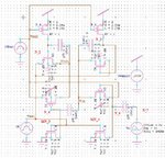
Capture.JPGULVinvcmCKT - Copy.JPG
 

from the base paper I get these points in page 6 of the PDF:
1. For ULV inverting current mirror, the nmos transistors are minimum sized and the width of pmos evaluate transistors (MQ2 and MQ3)are increased
I didn't get a page 6 from this paper, but I think this is ok.

2. The input capacitance to NMOS CSFG transistors are 200aF and input capacitors to PMOS CSFG transistors are increased (approximately 3 times the NMOS CSFG input capacitors) to match the transconductance of NMOS evaluate transistors(MQ1 and MQ4)
The capacitance of your coupling capacitors should be bigger than the input capacitances of the transistors, see Fig. 7. (page 4) of your base paper!

Based on this I changed the netlist as below, and the output current is around 200nA, which seems to match with Fig 5 in base paper.
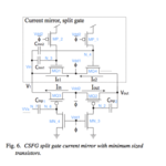
Either your schematic - which is virtually illegible, I can't even recognize the transistor and node designations! - or your netlist is corrupt, it doesn't match with Fig. 6. of the base paper. I already told you this before, but you didn't respond.

Here's what I got from parts of your netlist, but it doesn't match completely with your netlist. Seems you mixed up the nodes N_2 & N_4 (as already mentioned):
CSFG_split-gate_current-mirrors.png

Now is the output correct?
It looks better, but I think it can't be correct.
 

Hi erikl, sorry for the confusion, I am referring to my reply #19 of this thread in first page, where I have attached another base paper View attachment 2011-Ultra low-voltage CMOS current mirrors.pdf and this circuit I am simulating is Fig 4 (ULV inverting current mirror). Please give your inputs after checking the netlist.
 

Please give your inputs after checking the netlist.

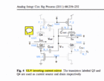
Hi deardeepa, sorry, too, for mixing up with the wrong schematic (Fig. 6 of the 2008 paper, resp. Fig. 3 of the 2011 paper). Your netlist is correct for the schematic of Fig. 4 of the newer paper (your schematic from posting #28 is not readable, i.e. its designations aren't recognizable, pls. always check your images before posting). Better provide something like this:
2011-Fig.4_ULV_inverting_current_mirror.gif

Just two notes now:

1. Is there a reason why you set the longer width of 900nm just for the PMOSFETs MQ2 & MQ3, and not for MP_1 & MP_2 ?

2. Why did you set Cinn1 & Cinp2 a factor of 500 (!) smaller than Cinn2 & Cinp1 ? They all have to feed the same input capacitance (1*drain + 1*gate), so I think they should all have the same capacitance, at least 100fF, better 200fF, I'd suggest.

Compare the voltages at nodes N_6 & N_7: Already with 100fF you loose some amplitude height at 2MHz input frequency.

Hi erikl, thanks for the response, from the 2011 paper I get these points in page 6 of the PDF:
1. For ULV inverting current mirror, the nmos transistors are minimum sized and the width of pmos evaluate transistors (MQ2 and MQ3)are increased
2. The input capacitance to NMOS CSFG transistors are 200aF and input capacitors to PMOS CSFG transistors are increased (approximately 3 times the NMOS CSFG input capacitors) to match the transconductance of NMOS evaluate transistors(MQ1 and MQ4)
Based on this I kept the width of MQ2,MQ3 as 900n, but I was not sure whether to keep same width for MP_1 & MP_2.
Similarly for capacitors I kept cinp1,cinn2 as 100fF and cinn1 and cinp2 as 200aF.
So with this the output is as below which seems to match with Fig 5 in base paper. Now is the output correct? Capture.JPG
If I am keeping all capacitors same value of 200fF then, the N_7 and N_6 nodes have similar voltages in both cases but only the current increases from 200n to 1.5u as in here Capture1.JPG
 
Last edited:

... from the 2011 paper I get these points in page 6 of the PDF:
There are no such items on page 6 - but I found them on page 4 :smile:

1. For ULV inverting current mirror, the nmos transistors are minimum sized and the width of pmos evaluate transistors (MQ2 and MQ3)are increased
Ok, fine.

2. The input capacitance to NMOS CSFG transistors are 200aF and input capacitors to PMOS CSFG transistors are increased (approximately 3 times the NMOS CSFG input capacitors) to match the transconductance of NMOS evaluate transistors(MQ1 and MQ4)
Based on this I kept the width of MQ2,MQ3 as 900n, but I was not sure whether to keep same width for MP_1 & MP_2.
Similarly for capacitors I kept cinp1,cinn2 as 100fF and cinn1 and cinp2 as 200aF.

Ok, but why, then, did you increase them 500 times, and not approximately 3 times?
BTW: In Fig. 3, p. 4 (different schematic: CSFG split gate current mirror) they used 2fF & 6fF cap values.

So with this the output is as below which seems to match with Fig 5 in base paper. Now is the output correct?
What's correct? You think: like in the paper? Yes, looks quite good!

If I am keeping all capacitors same value of 200fF then, the N_7 and N_6 nodes have similar voltages in both cases but only the current increases from 200n to 1.5u as in here
And looks even better. At least for the evaluation of the sinusoidal envelope curves.

Good luck!
erikl
 

Ok, but why, then, did you increase them 500 times, and not approximately 3 times?BTW: In Fig. 3, p. 4 (different schematic: CSFG split gate current mirror) they used 2fF & 6fF cap values.

What's correct? You think: like in the paper? Yes, looks quite good!
And looks even better. At least for the evaluation of the sinusoidal envelope curves.

Hi erikl, In fig 5a on page 6, the graph showing Iin and Iout has pulses of same height (2*10-7 to -2*10-7). So my simulation output should resemble that, so only I thought keeping capacitor values as i said gives similar waveform like in paper. If i reduce the PMOS below 100fF current level is much less than mentioned in paper.
 

Dear deepa,

so you successfully manipulated all these input values until you achieved the same output results as the paper. Well done! Congratulations!

And now: what's the whole purpose of this? What do you actually want? How will you go on? Where do you need these mirrors?
 

Hi erikl,

I am graduate student and just trying to implement the mirror for my course project work. So I am in confusion whether I should follow the inputs in paper and give the results which I get as output in the project report or try to match the output in paper by changing the design parameters(W/L, Capacitor values), because I am using a different model file but for same 90nm technology. sorry If I am bothering you too much. But really a lot of thanks from my side for helping me out.
 

Status
Not open for further replies.

Similar threads

Part and Inventory Search

Welcome to EDABoard.com

Sponsor

Back
Top